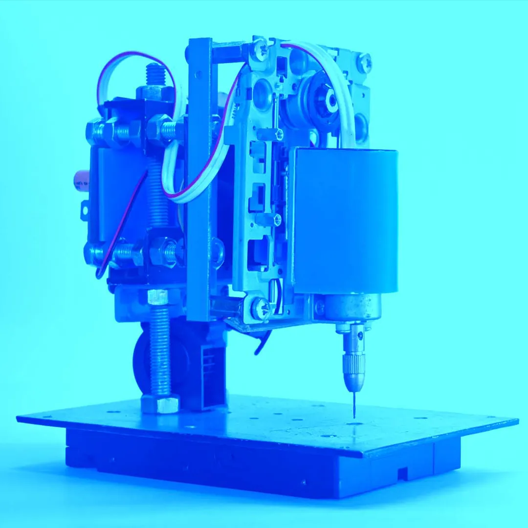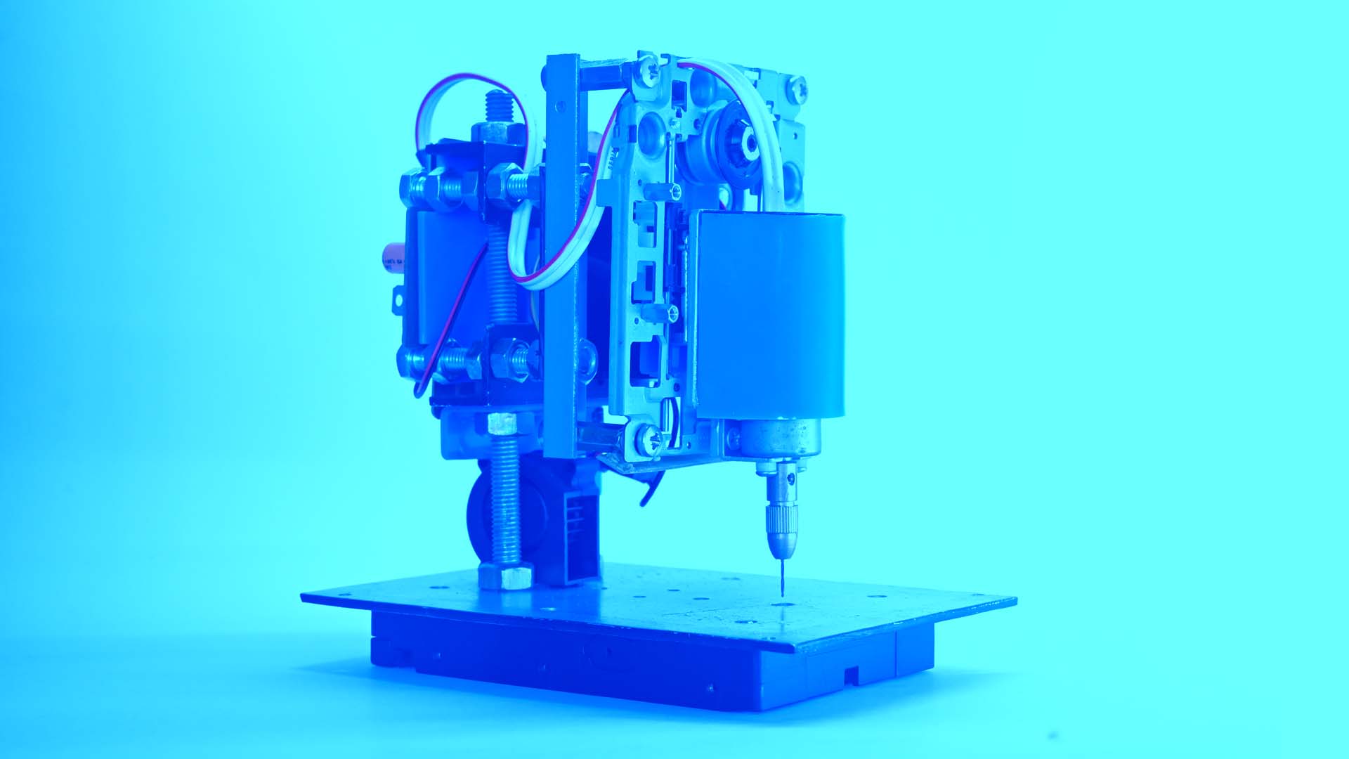
Simple DIY PCB drill machine.
When it comes to PCB fabrication, a good PCB drill is necessary to finish the fabrication quickly and perfectly.
I’m demonstrating my fully customizable, do-it-yourself PCB power drill. This updated drill includes new features: a pedal press drill, an air blower, and LED lighting for the drill area. A CD drive mechanism is essential for its primary functionality.
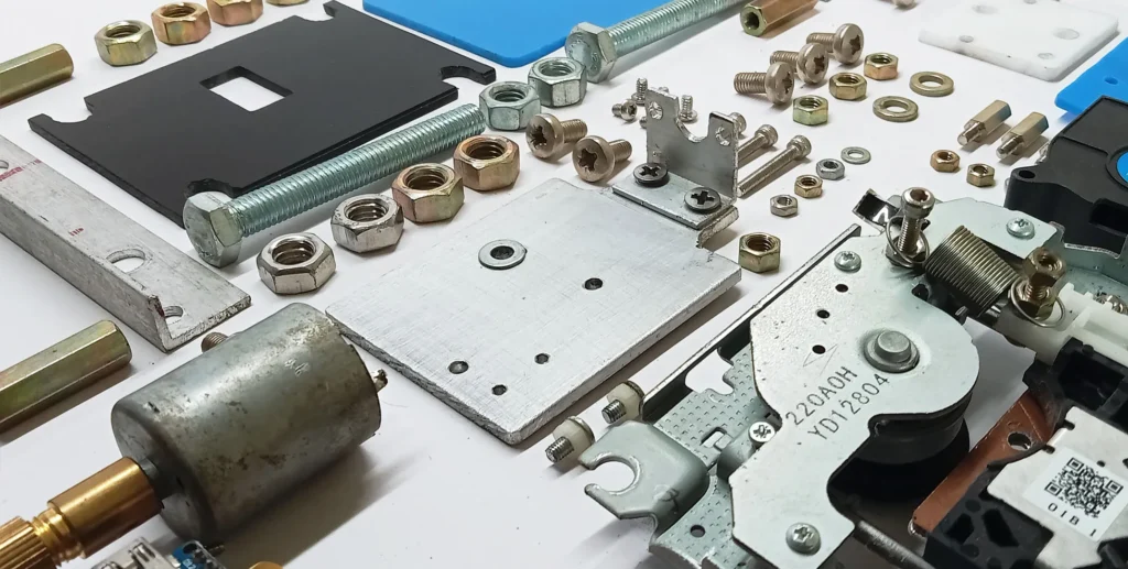
Hardware and supplies I used include a CD drive mechanism, Arduino, air blower, LED strip, aluminum angle and plates, acrylic sheet, thread rod, nuts, bolts, and screws.
CD drive modification
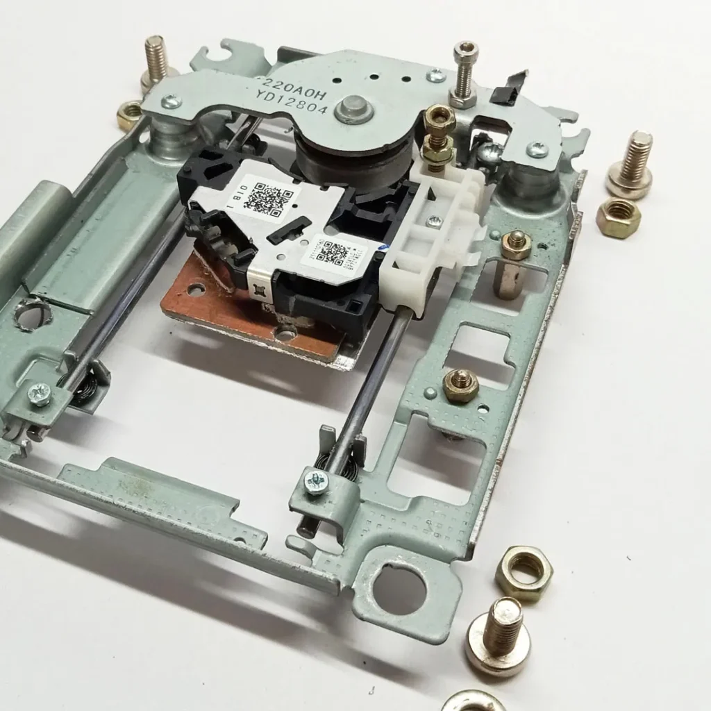
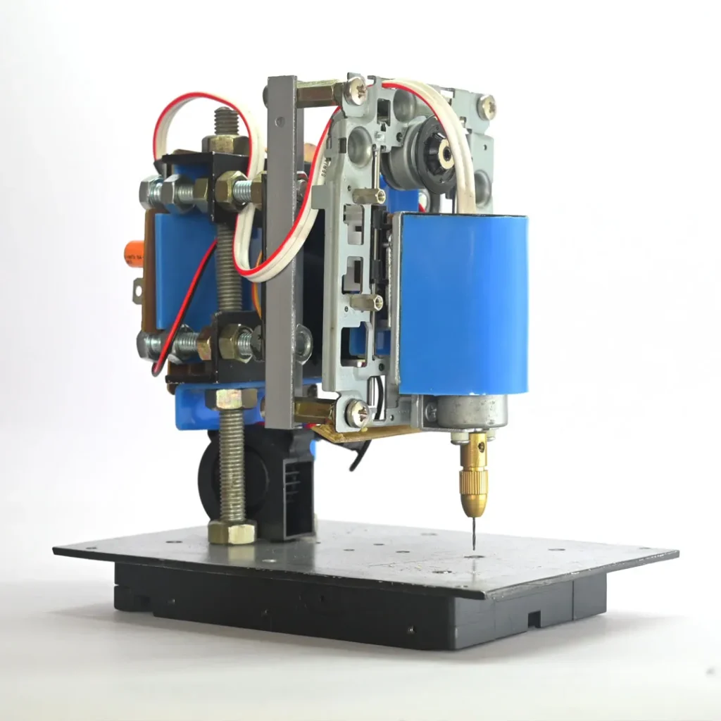
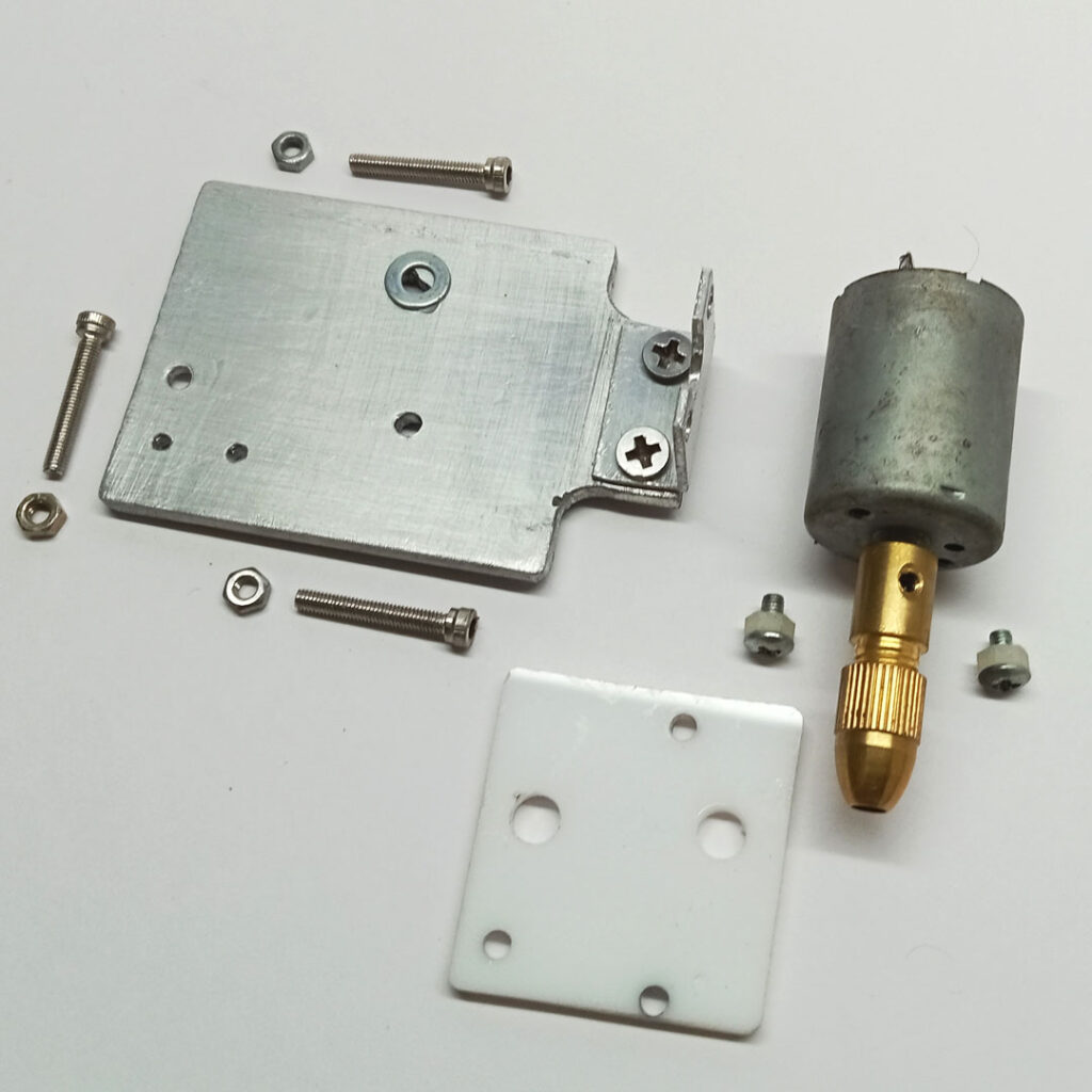
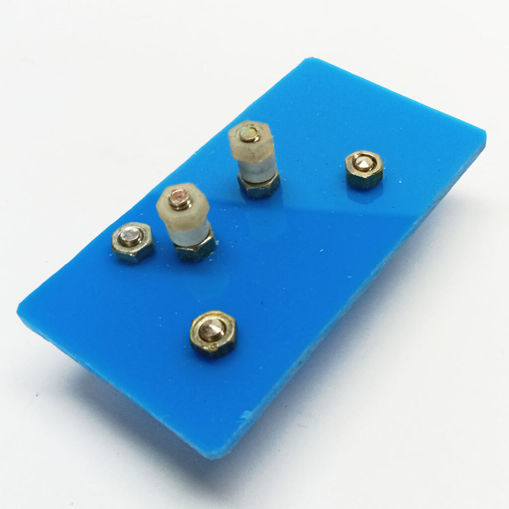
I removed the laser head from the CD drive and converted the space into a flat mount for the drill motor. I used a piece of aluminum and a plain PCB board, fastening them with a couple of screws.
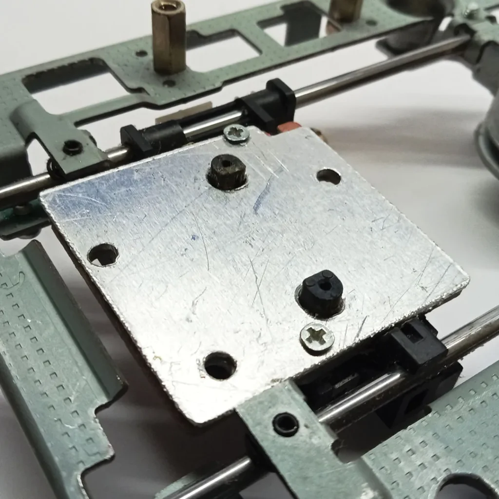
Fixing Dc motor
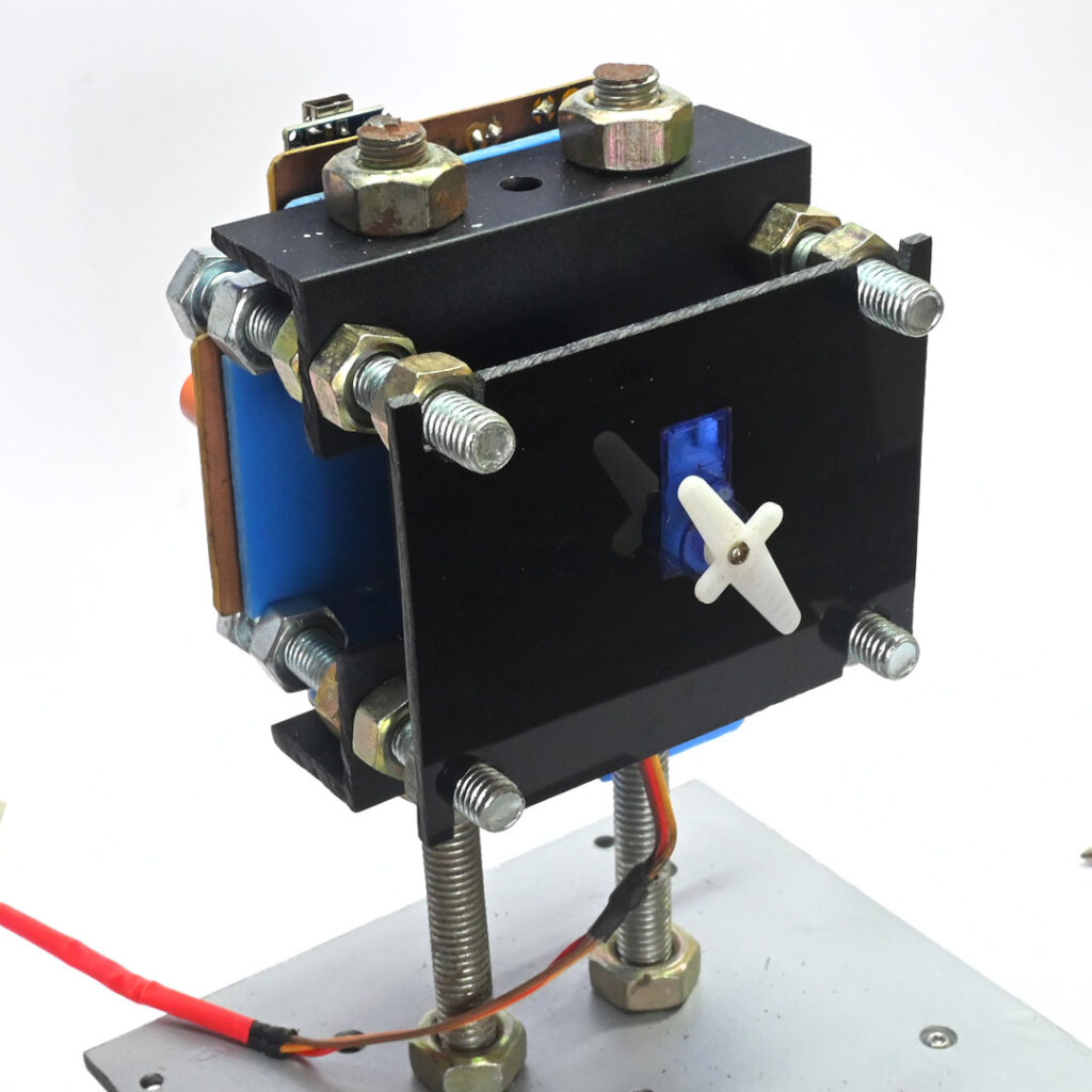
Drill-pressing system
A servo horn is placed between two roller shafts to press and release the driller.
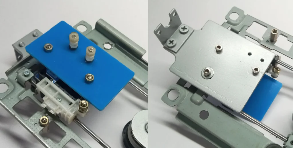
Front and rear views of the completed drill press/release system.
Column and base of the driller
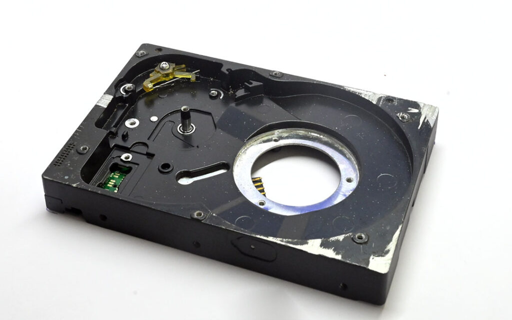
I employed a hard disk case as the primary base to enhance stability during drilling. Its substantial weight effectively reduces vibrations, ensuring a steady foundation for the operation.
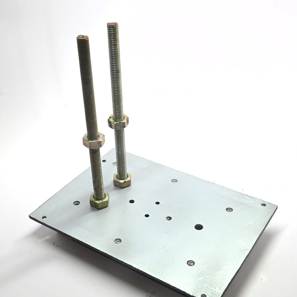
A 4mm thick aluminum plate is attached to the hard drive case to create a work area and a 10mm thread bar mounted on the plate serves as a vertical column.
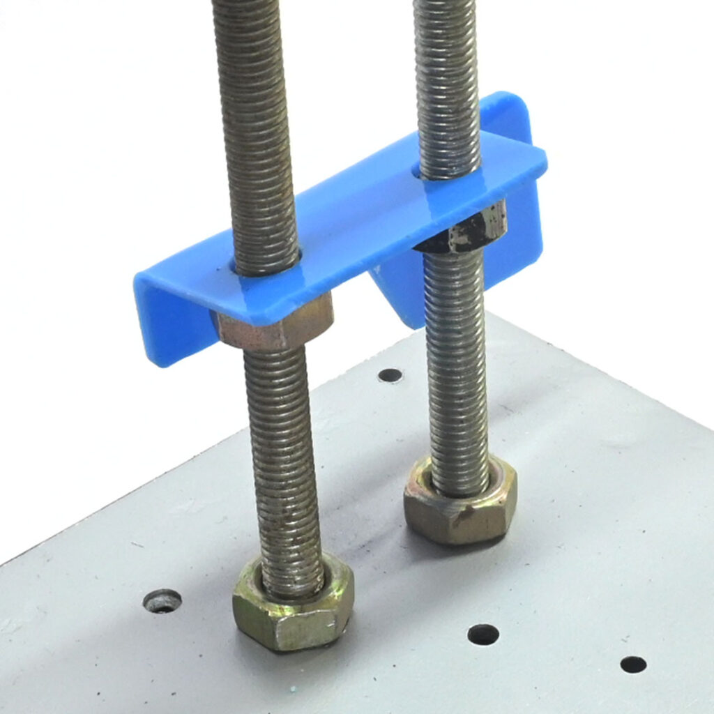
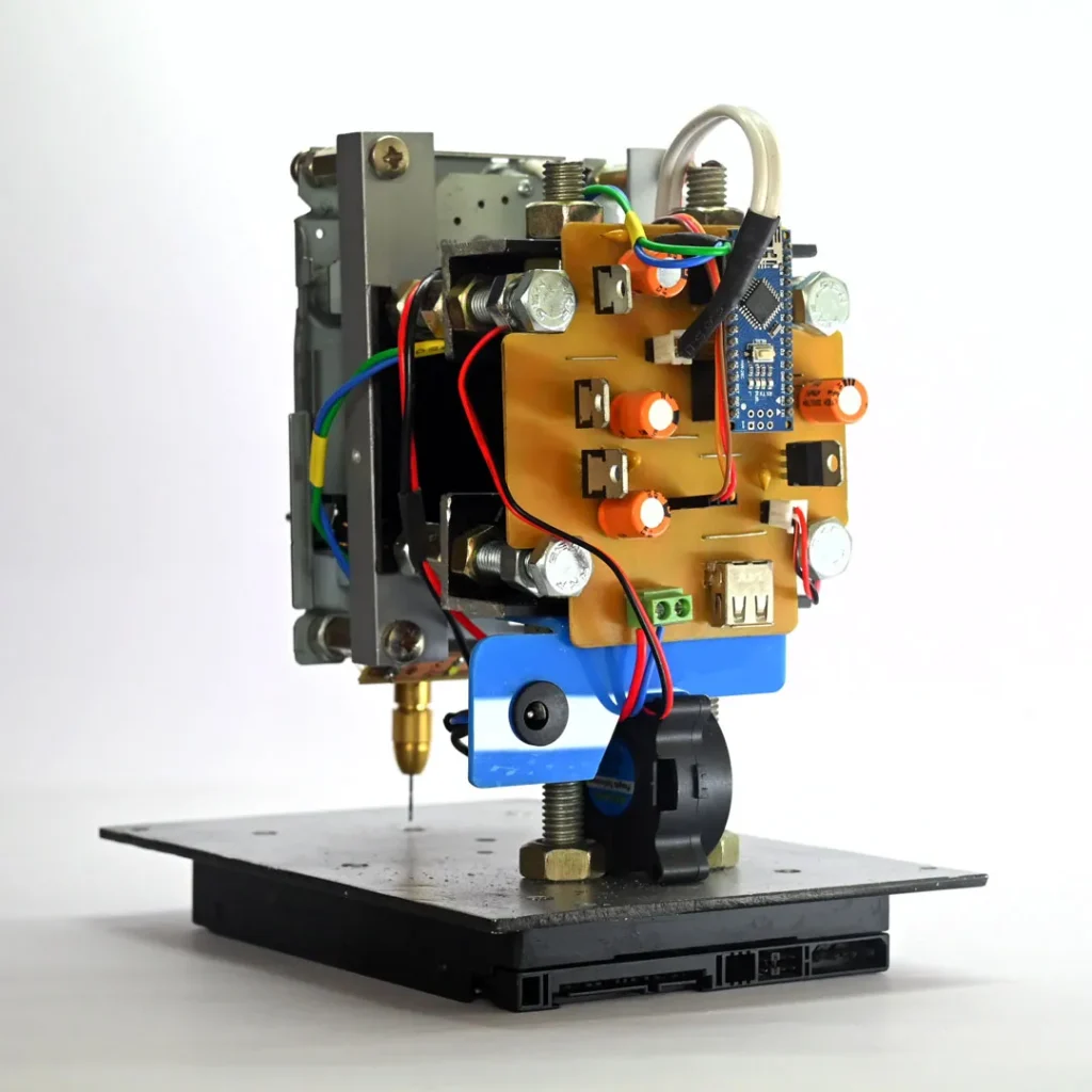
A piece of acrylic is bent and inserted into the column rod and it is used as a DC power plug holder.
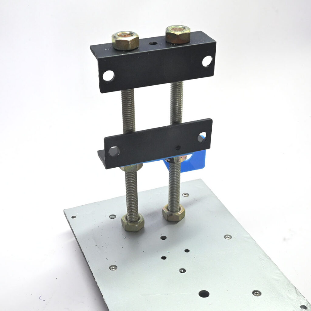
To create a horizontal beam for mounting the drill mechanism, I fastened two aluminum “L” angles to the vertical column.
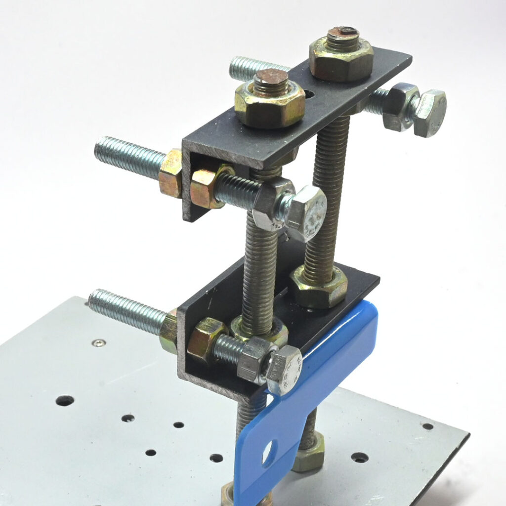
Four 70mm M8 bolts and nuts are used to build four beams. The rear side of the beam is used to mount the circuit board.
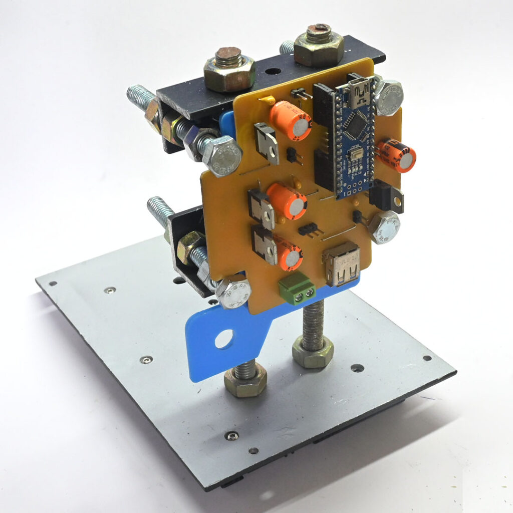
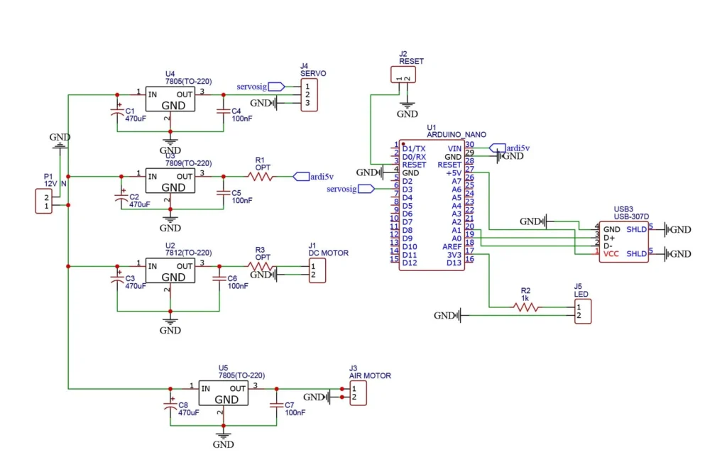
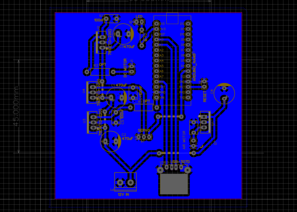
The circuit board includes an Arduino Nano and a power supply for the blower, LED, and drill motor. Arduino is used for pressing and releasing the drill.
Circuit and Arduino code
#include <Servo.h>

//Include the servo library

Servo servo1;

int joyX =0;
int joyY =1;


int joyVal;

void setup()
{ //attaches our servos on pins PWM 5
 servo1.attach(5);
}

void loop()
{
  //read the value of joystick (between 0-1023)
  joyVal = analogRead(joyX);
  joyVal = map (joyVal, 0, 1023, 0, 180); //servo value between 0-180
  servo1.write(joyVal); //set the servo position according to the joystick value

  joyVal = analogRead(joyY);
  joyVal = map (joyVal, 0, 1023, 0, 180);
  servo2.write(joyVal);
  delay(15);
}
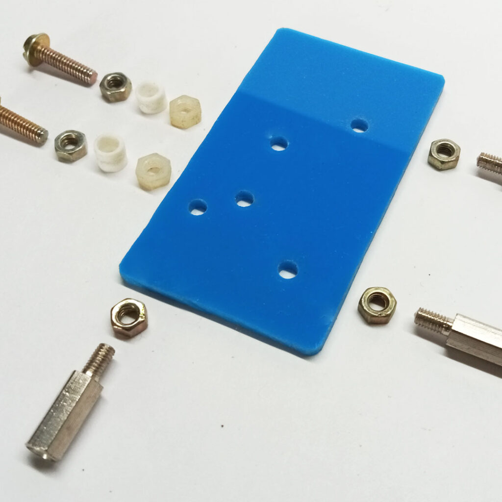
I attached a servo motor to an acrylic plate and positioned it on the front side of the beam.
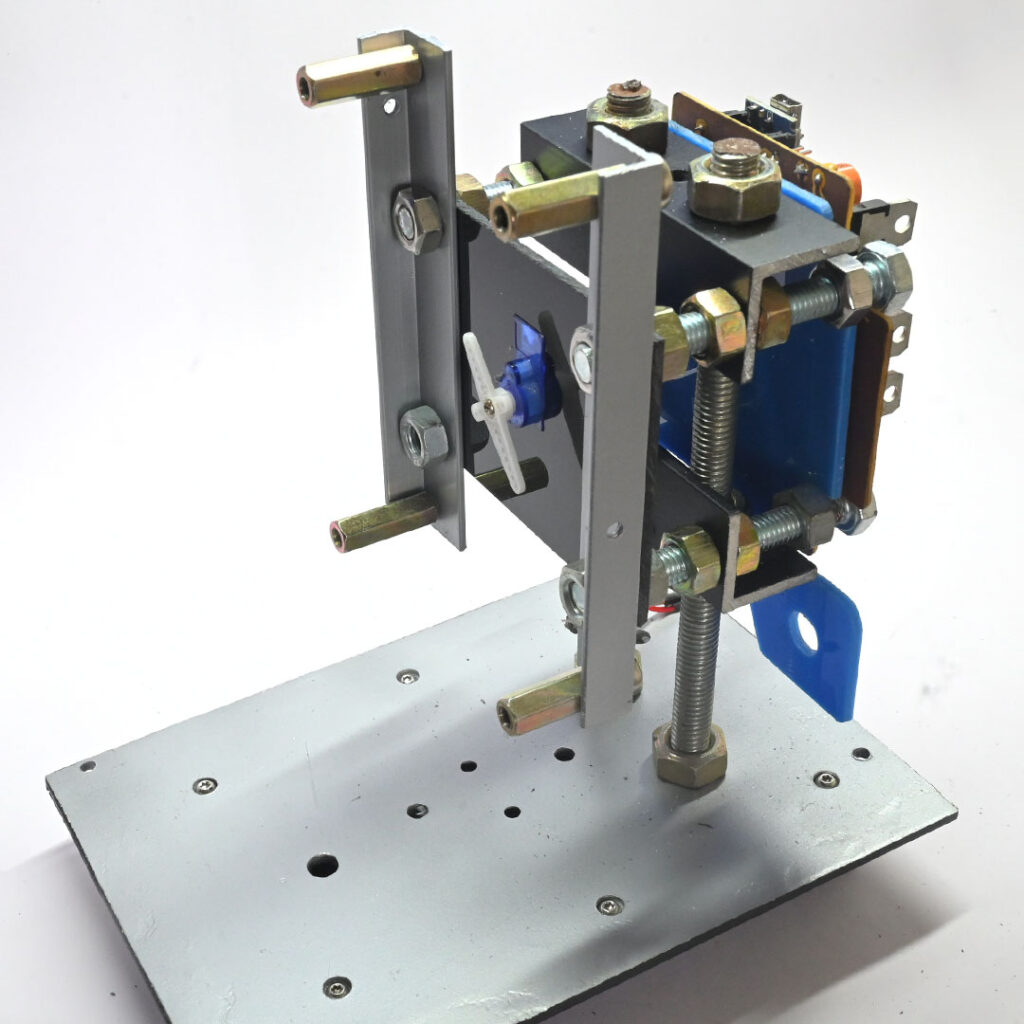
Another pair of “L” angles are vertically fixed at the end of the beam, with four spacers attached at the ends of each aluminum angle. The drill mechanism will be mounted on these four spacers.
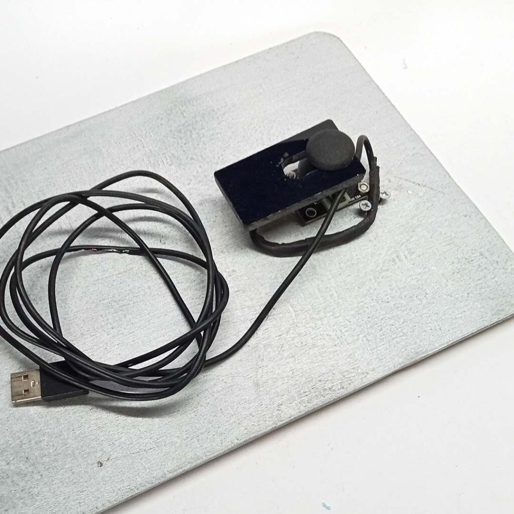
Pedal for drill press
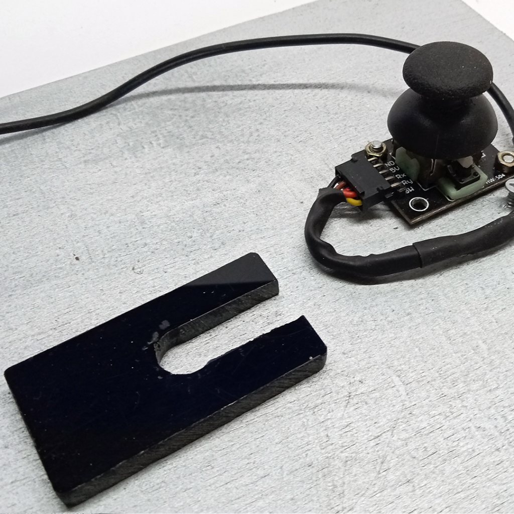
A drill press pedal is created using a joystick module connected to the Arduino via a USB connector.