
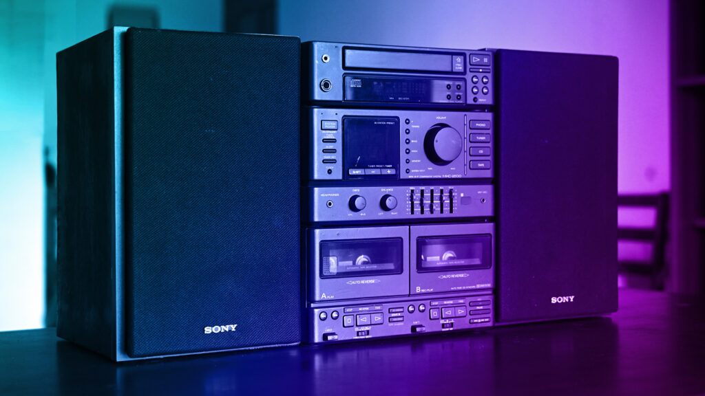
A compact design and robust sound quality audio system Sony MHC-2500..
Restoring and Exploring 90s Sony MHC-2500 Mini Hi-Fi System, here I’m sharing a restoration and exploration of the 90s Sony MHC-2500 Hi-Fi system. Analog music until the 90s represented a genuine love for quality sound and a unique satisfaction in experiencing music. Cassette decks, vinyl turntables, and Hi-Fi systems from that era were crafted with a dedication to sound quality. They offered a rich, immersive listening experience that deeply resonates with audiophiles. Appreciating analog players means valuing the artistry in both the music and the devices. These machines were built to last, showcasing meticulous attention to detail and a commitment to delivering the best possible sound.
The 90s were my teenage years, and they marked the peak of the cassette music era. Cassettes were hugely popular back then, along with Walkman, medium-format tape recorders, and decks. I was passionate about both music and audio equipment, using various Walkman, tape recorders, and amplifiers. I dreamt of owning a big music deck (like a Sony MHC-2500 Mini Hi-Fi System), but at that time, it cost around Rs 20,000 to 30,000, which was beyond my reach. Despite this, I managed to achieve good audio output with a reasonably high-end amplifier. Subwoofers weren’t well-known then, so I used bigger speakers in large wooden enclosures for good bass. I even mounted speakers in mud pots as a creative solution, which was creative for those days.
A Dream Fulfilled: Acquiring the Sony MHC-2500
I’m excited to share the story of how I fulfilled a childhood dream by acquiring the Sony MHC-2500 Mini Hi-Fi. While working in Bangalore in 2020, I accidentally found a small electronics repair shop filled with old radios, tape recorders, and TVs. My eyes caught a cassette deck on a rack, which was being used to play a radio station. I asked the owner if it was his. He confirmed and mentioned that the cassette and CD players were broken, and that cassettes are rare now. I asked if he would sell it, and he offered it for Rs 2,000. Without hesitation, I agreed, paid him, and finally took home my dream Hi-Fi system.
It was the Sony MHC-2500, a mini Hi-Fi system with a cassette deck, CD player, and AM/FM radio, was a dream of mine since my teenage years. Known for its compact design and robust sound quality, holding it felt like reconnecting with my past. Now, I’m excited to restore it to its former glory and relive the rich, immersive sound that defined those days.
The Condition and Initial Inspection
Despite being second-hand, the unit was in good condition, with no external damage—just some dust and moisture. The CD player wasn’t working due to a burnt power circuit board, and one of the cassette decks was also faulty. However, the middle power and amplifier section was operational, and the sound quality was incredible, surpassing modern digital players. I decided to temporarily convert the CD section into a Bluetooth receiver using the same deck, so I could keep the system in use.
Now, I’ve decided to go a step further and completely revamp the system. The plan is to fix the cassette player and transform the CD section into a high-quality pre-amp.

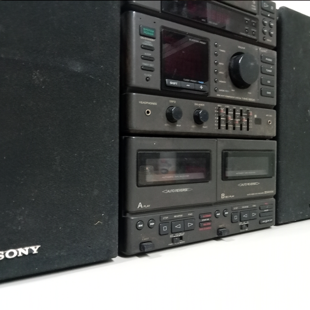
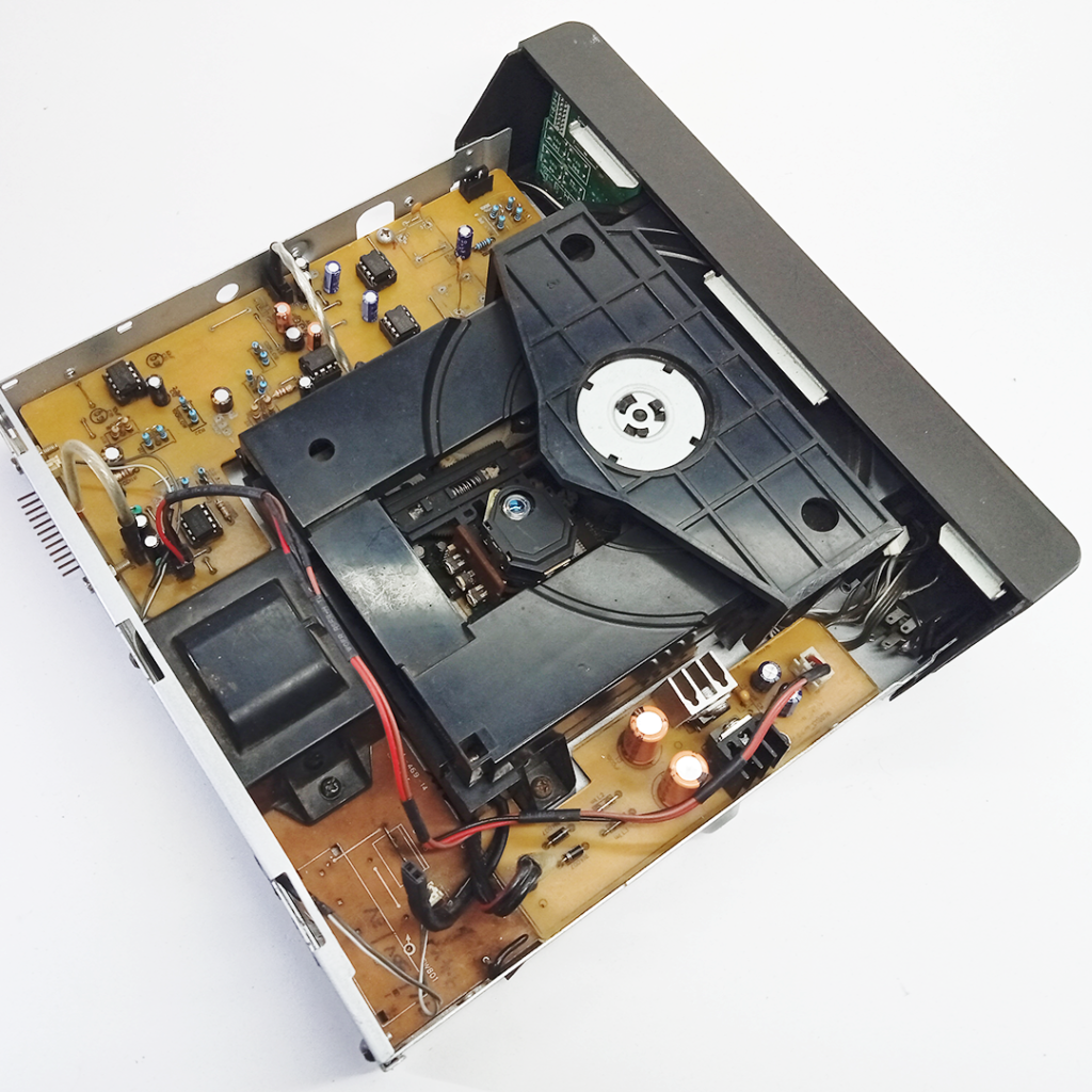
This was condition before restoring, I completely disassembled the internal components for thorough cleaning, removing dust and moisture. I troubleshooted and repaired the non-functional cassette deck by replacing the belt and cleaning the tape heads. I also painted the chassis, polished the panels, and constructed new wooden enclosures for the left and right speakers.
This system having three components/sections.
1. Receiver, Model: STR-H100.
2. Cassette Deck, Model: TC-H500
3. CD Player, Model: CDP-S39.
4. Speaker System (L&R) Model: SS-H2500.
1. Receiver, Model: STR-H100
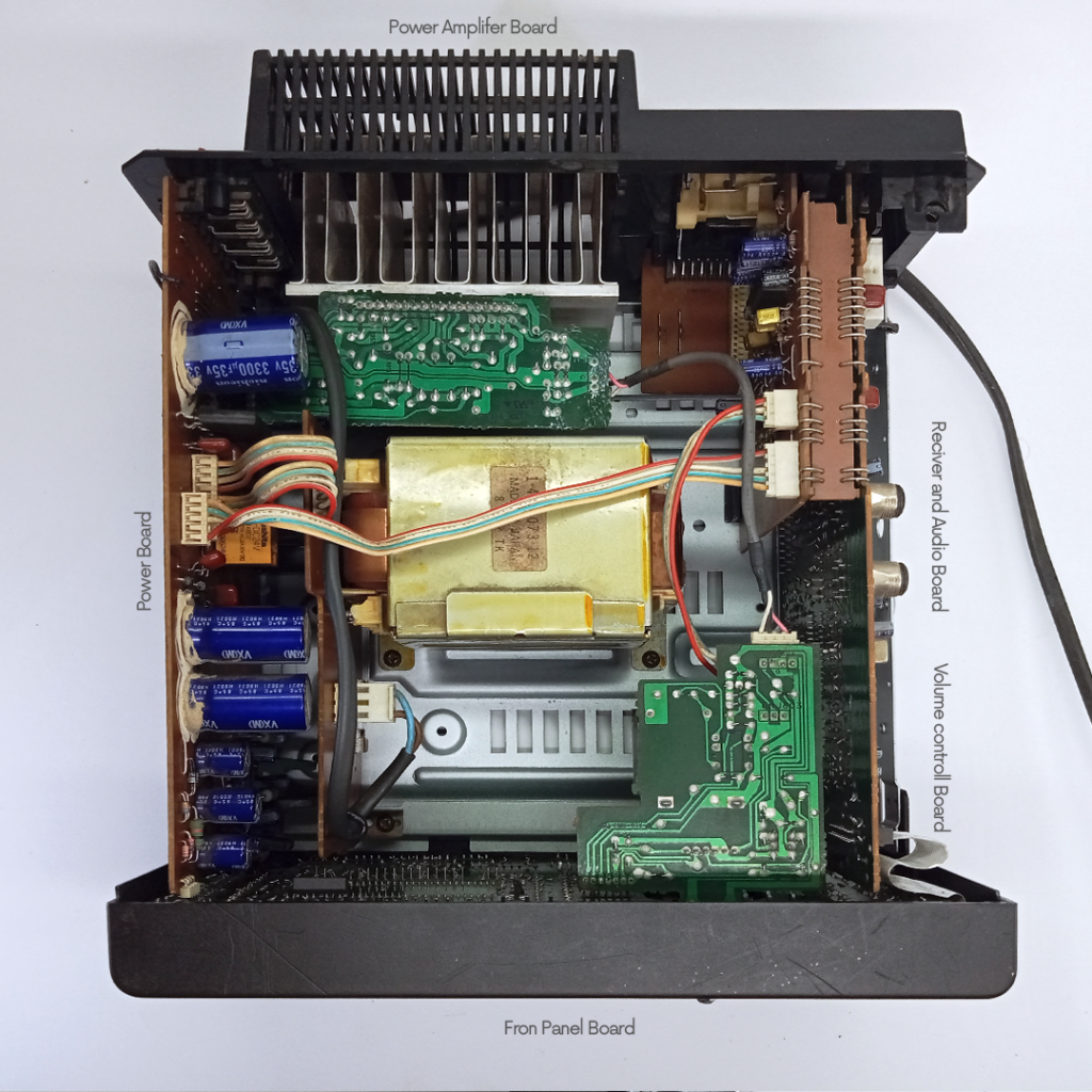
The receiver section of this system contains several critical components: the Power, Tuner, Audio , Power Amp, Transformer, Volume Control, and Control Panel. Upon opening the top cover, I was immediately impressed by the meticulous planning and elegant design of the internal layout. Each board and component is thoughtfully arranged and precisely positioned, showcasing an impressive level of craftsmanship.
I carefully disassembled all the parts, finding them in good condition overall, with no significant defects, only a layer of dust accumulated over time. Using a brush, I removed all the dust from the panels and boards. I cleaned the front plastic panel with soap and water to remove all dust and moisture and metal chassis were in good condition. For restoration, I chose silver for the metal chassis and applied a matte clear spray to the panels to restore the dried-out surface.
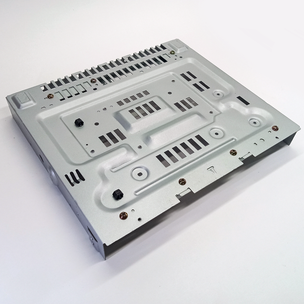
Here’s the bottom view of the chassis, after freshly coated with two layers of silver spray paint.
Transformer
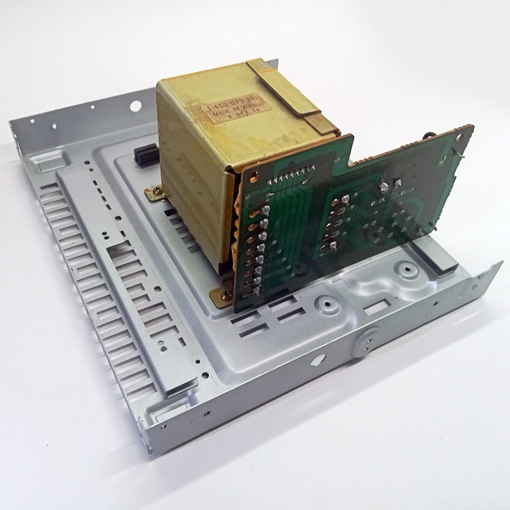
Transformer board mounted on chassis, it specified handles input voltages from 110 to 240 AC, providing outputs of 20V, and 16V, along with a ground connection. It has eight output terminals, three of which are not connected, and a fuse between the input AC and the transformer.
Power Amplifier
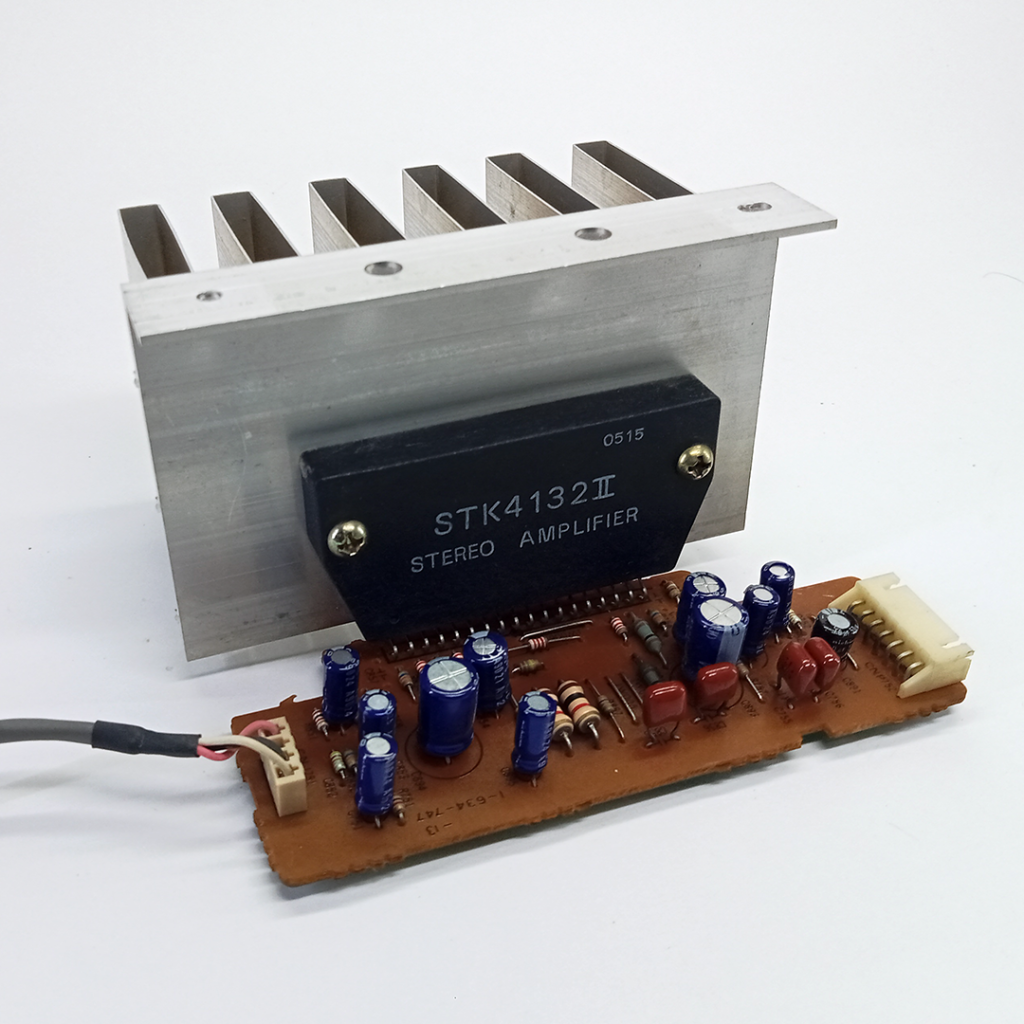
This is the power amplifier unit featuring the STK 4132, a high-performance audio IC. It delivers up to 100 watts per channel into an 8-ohm load with low distortion, ensuring clear and accurate sound. The IC has built-in thermal protection to prevent overheating and damage. It connects externally via an audio input and a power output for the left and right speakers. The output connects to a 3-way, 3-driver loudspeaker system, featuring a 45W bass driver, a midrange driver, and a tweeter.
Back Panel
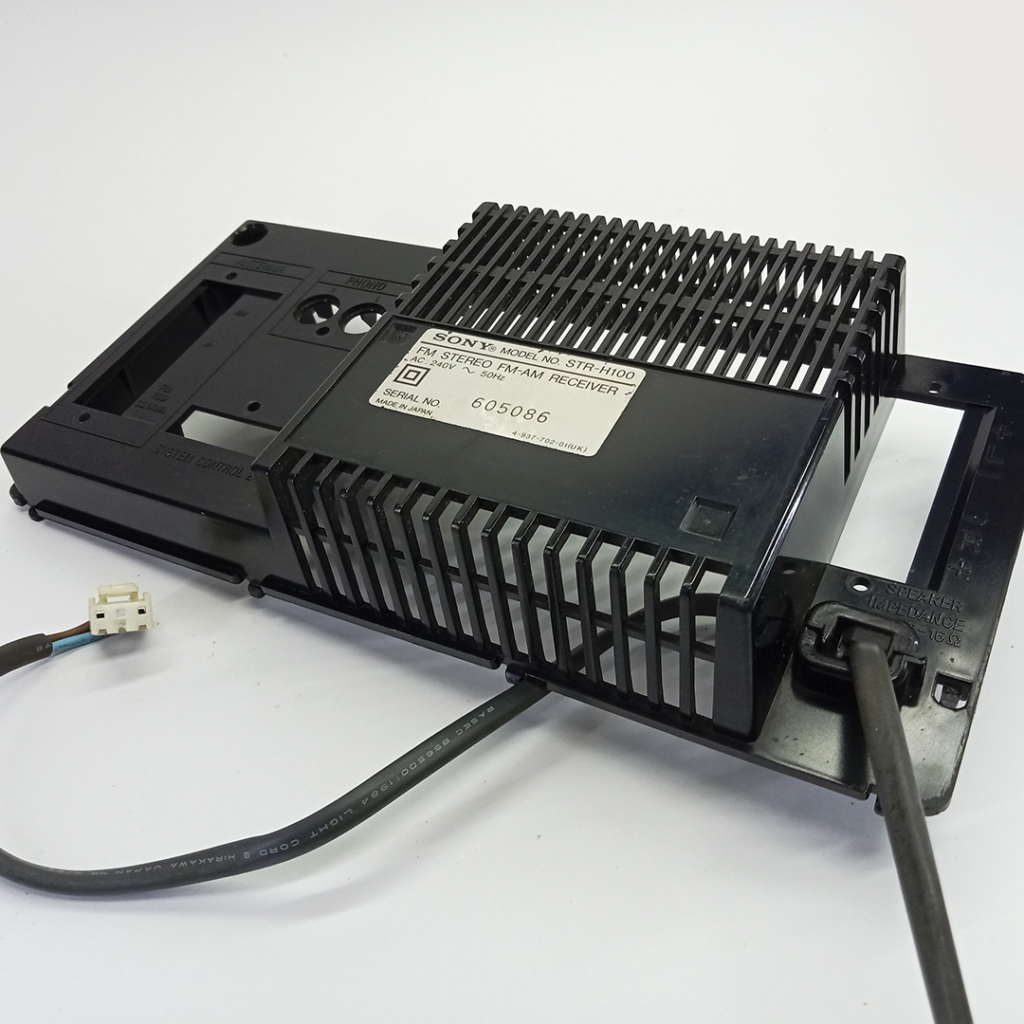
This is the back panel, which provides connections for audio output, phono out, radio antennas, and AC power input.
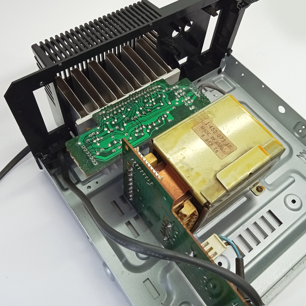
I installed transformer, power amplifier board and the back panel. The power amplifier board is mounted to the chassis with screw through heat sink, while the back panel is fixed at rear of the chassis.
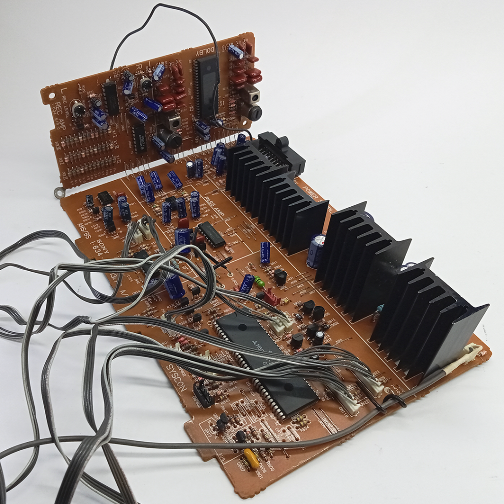
Power Board
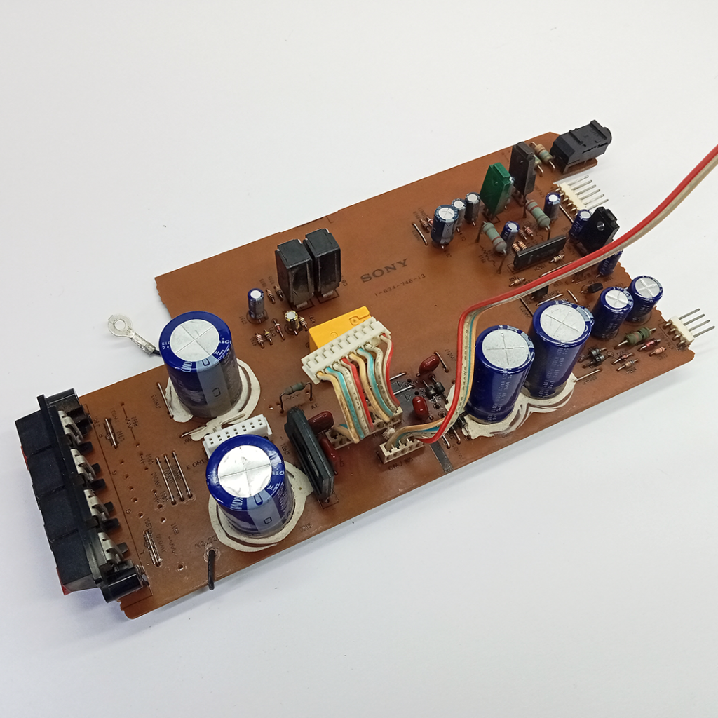
This power distribution board also includes speaker and headphone outputs. The power supply circuit features an ultra-fast recovery diode (RBA-402), a pair 2.2A breaker, a relay, and an M5230L variable output regulator IC. Additionally, there are two sets of connections to the front panel, which contains controls for the power on/off switch, display, radio control, Dynamic Bass Feedback (DBFB), volume control, and an equalizer, among other functions. It also provides power supply and audio input connections to the power amplifier board.
Tuner Board and Audio Board
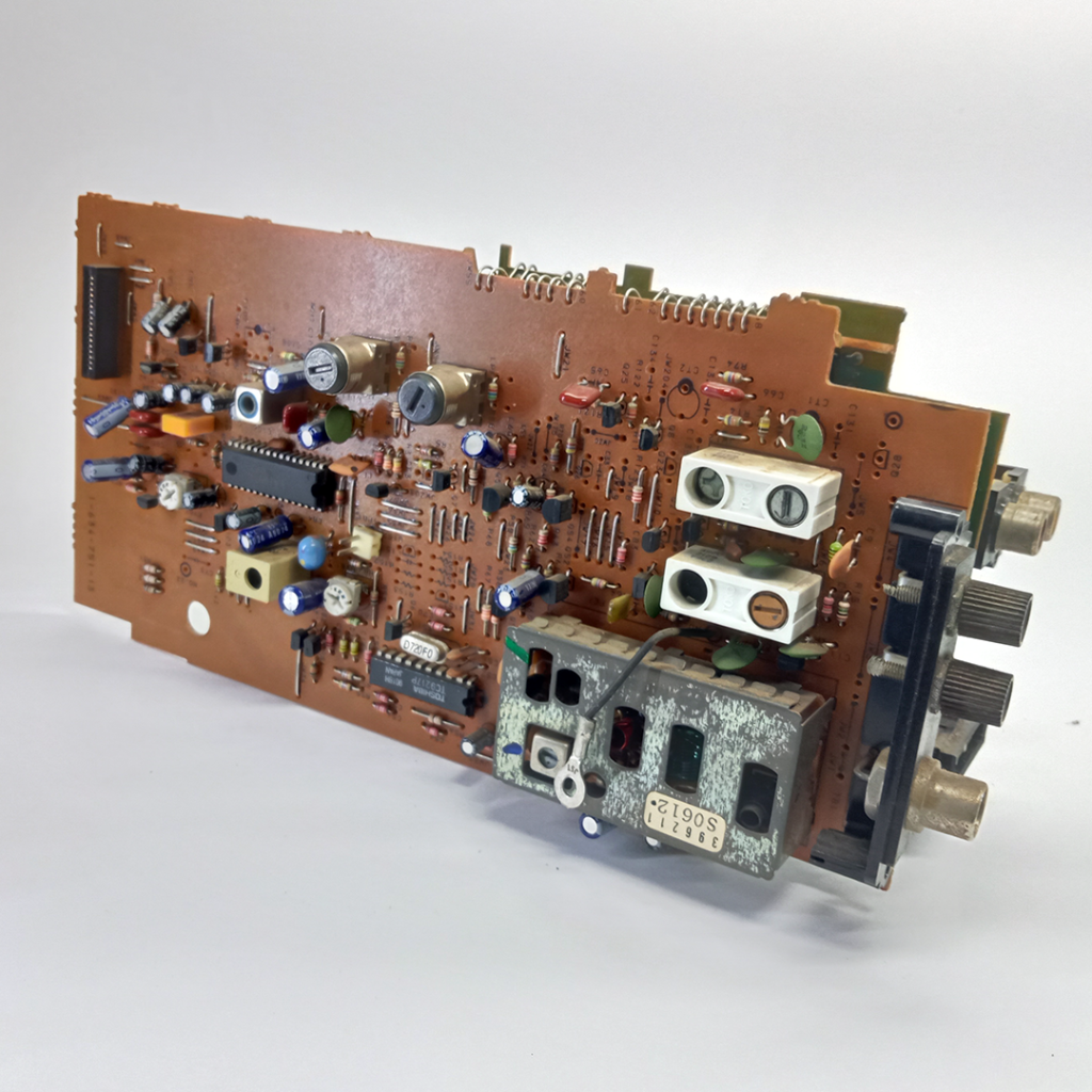
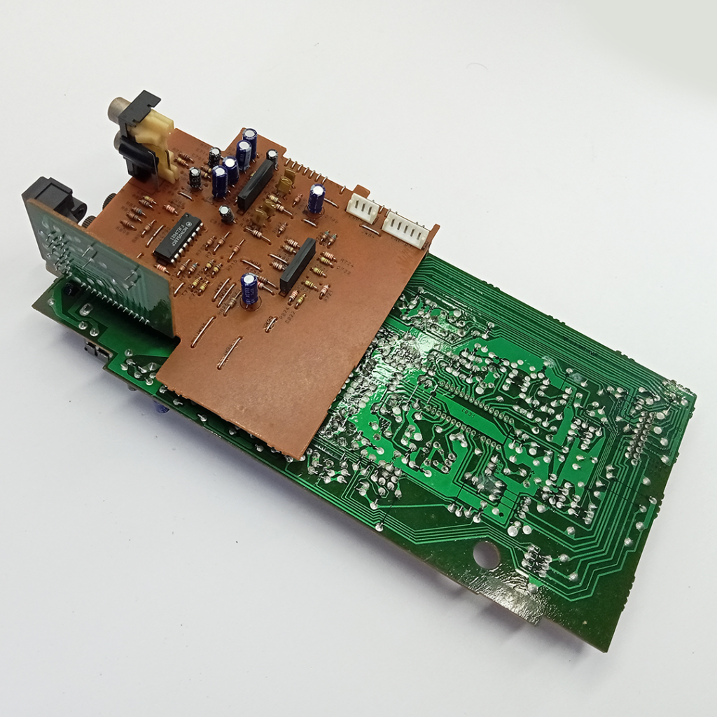
The tuner board and audio board are positioned one behind the other. The tuner board utilizes the LA1851N for receiving AM and FM stations, along with the TC9217P – a digital volume control IC. From this receiver board, an FCC ribbon cable connects to the front control panel. Also tuner board which includes AM and FM antenna jacks. On the audio board, the primary component is the phono amplifier board, which features the M5218AL for stereo audio mixing and processing. Additionally, the dual 4-channel analog multiplexer/demultiplexer IC14052BCP is employed for signal switching and routing. Audio board also connected to the system control connections board.
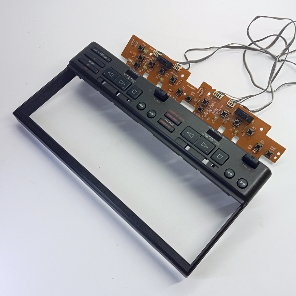
Front-end control panel and circuit board
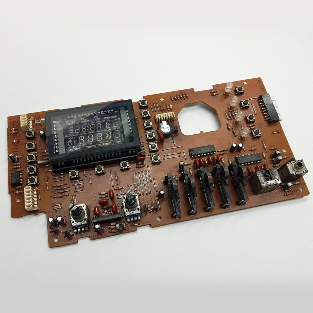
The panel board having controls for the power on/off switch, Fluorescent Indicator Tube, radio control, Dynamic Bass Feedback (DBFB), volume control, equalizer, IR receiver, mic jack among other functions. The board also has an equalizer circuit with controls for 12 kHz, 4 kHz, 1 kHz, 400 Hz, and 100 Hz frequencies.
Volume Control Board
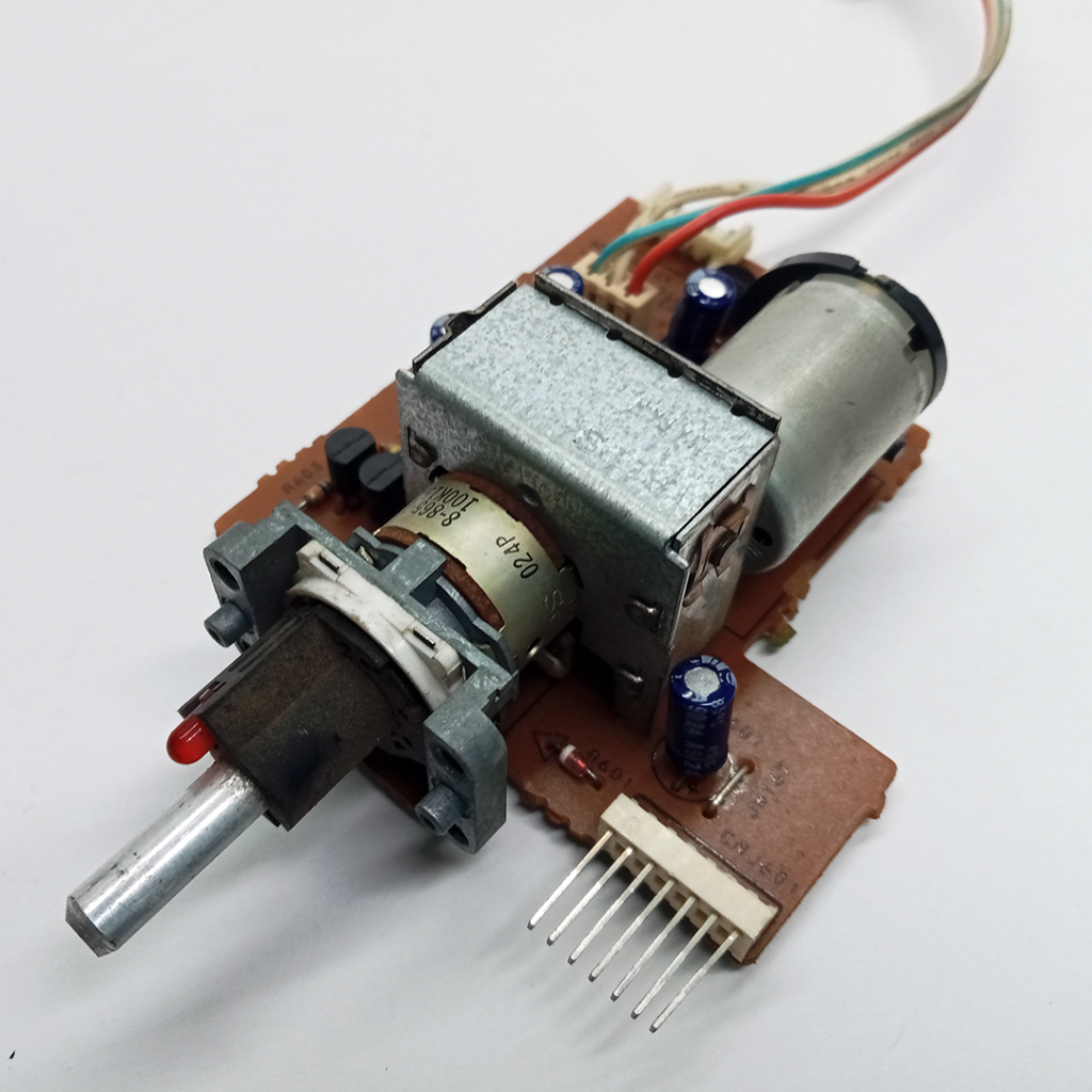
The volume control board, which is connected to the panel board, receives audio signals from the panel board and sends them to the power amplifier board.
After installing all the boards, components and wire connections on receiver section.
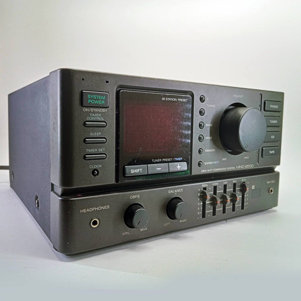
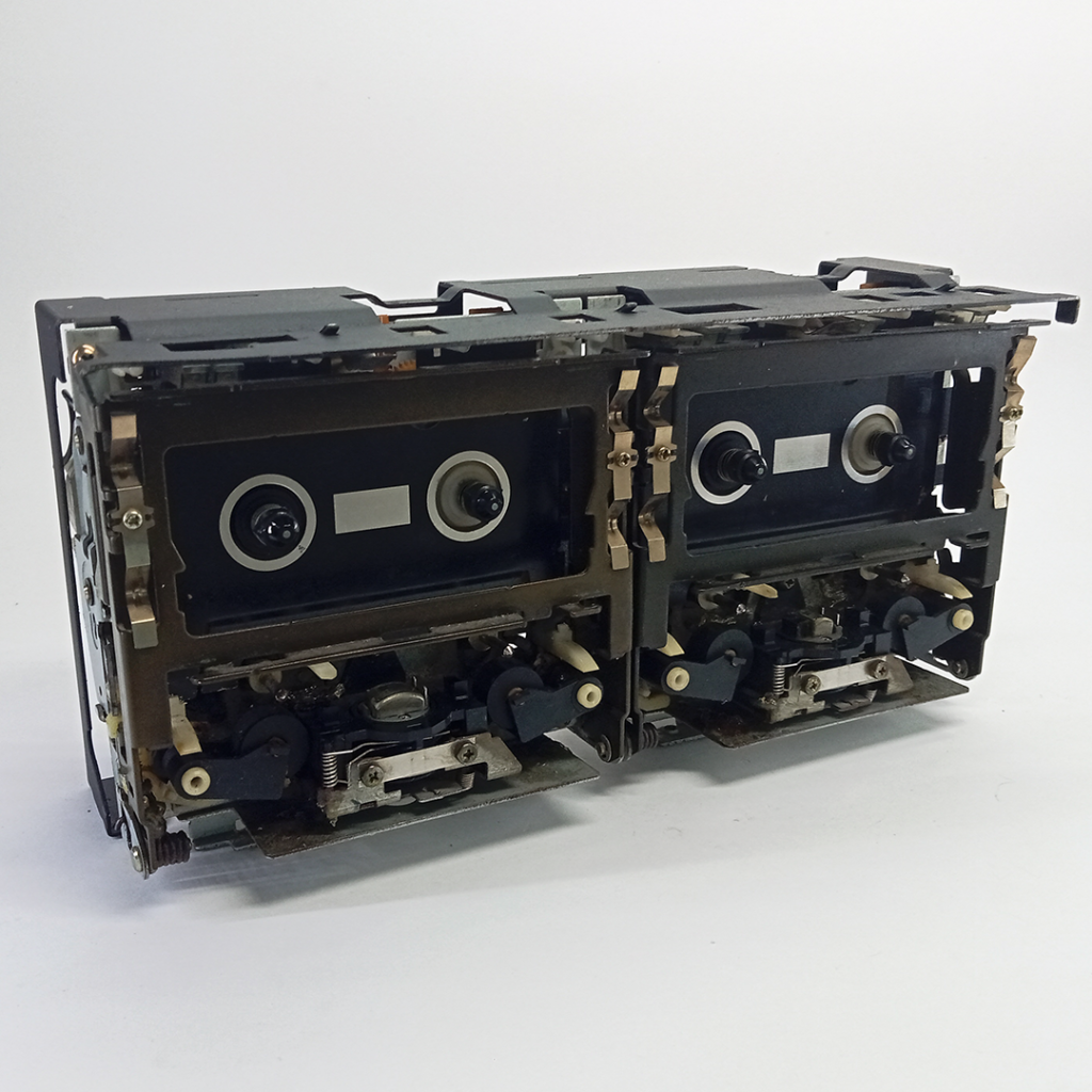
2. Cassette Deck, Model: TC-H500
In Sony MHC-2500 Mini Hi-Fi System the cassette deck includes two main decks, A and B, along with drive mechanisms and audio boards, enabling both recording and playback of cassette tapes. It offers features such as Dolby B and C noise reduction for clearer sound, a built-in timer, and an auto-reverse function. Instead of conventional mechanical control levers, it uses tactile switches for play, forward, reverse, and stop functions.
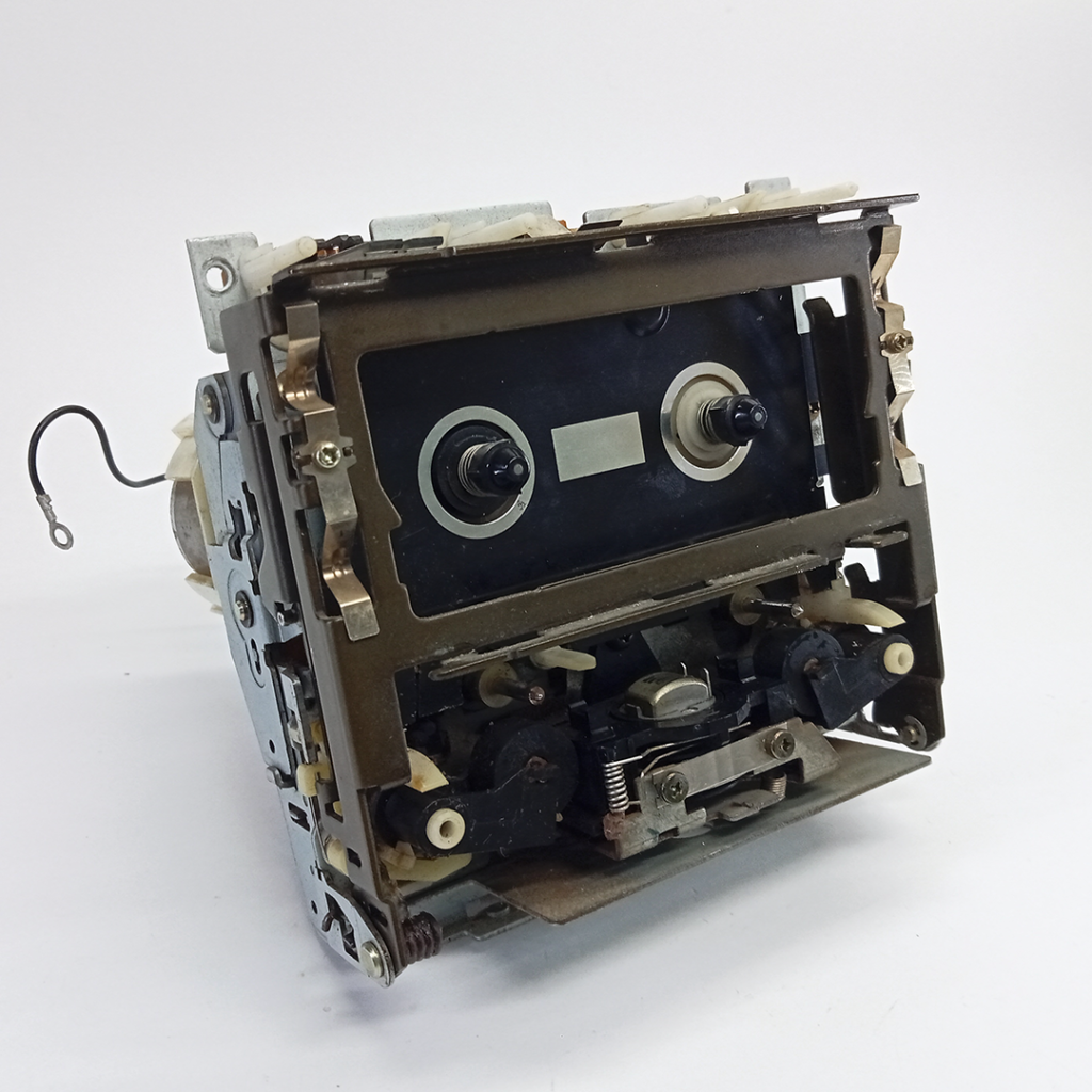
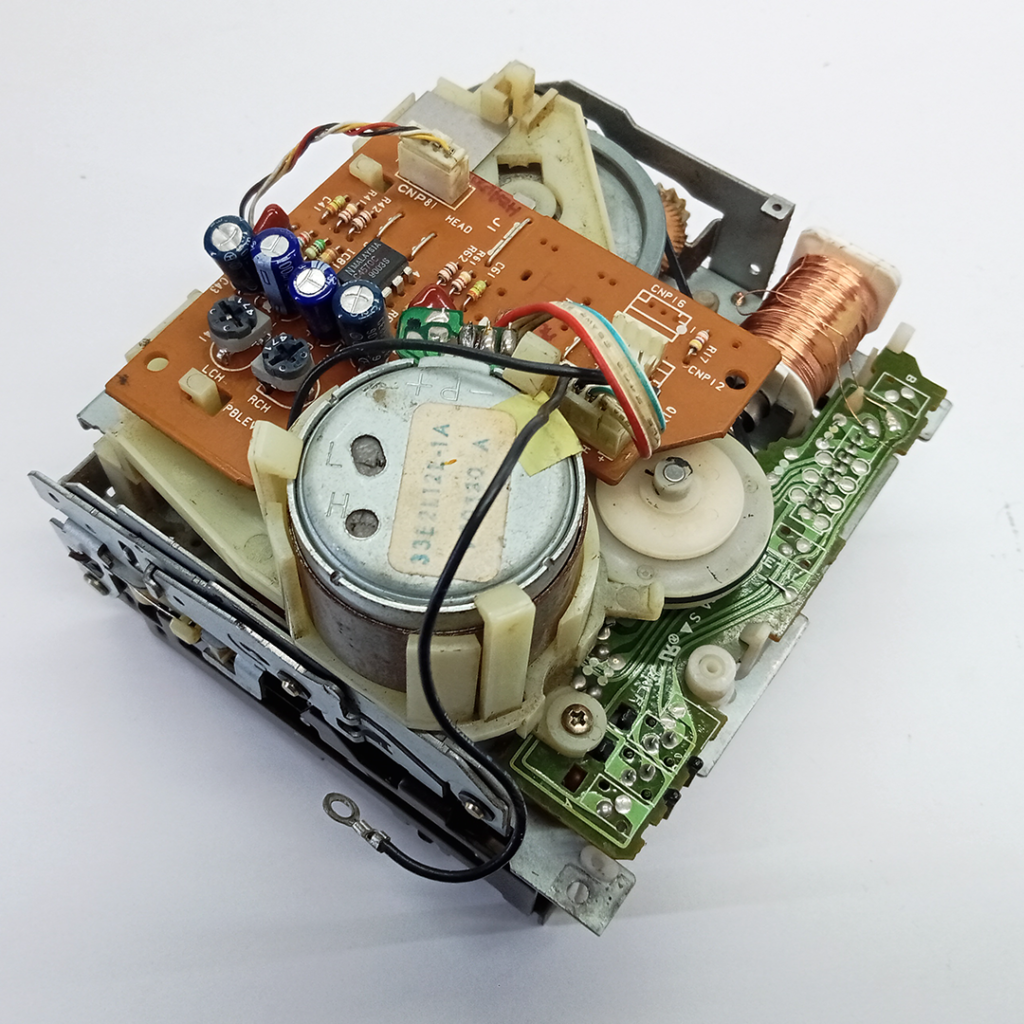
Deck A features a playback system equipped with an auto-reverse head mechanism and a mechanical drive board. The board features a magnetic head preamp board utilizing the UPC4570C, a high-speed and high-quality audio signal processing IC with dual ultra-low-noise, wide-band op-amps. Additionally, it includes a leaf switch coil with its drive board.
Deck B featured playback, erase record, and auto reverse head system. This deck also has the same magnetic head preamp board with the UPC4570C. In addition, it incorporates a record bias oscillator using 2SC2001 transistors, which is for cassette tape recording systems. Its primary function is to generate a high-frequency bias signal that enhances the quality of audio recordings on magnetic tape. Like Deck A, it also includes a leaf switch coil with its drive board.
Replacing Drive Belt
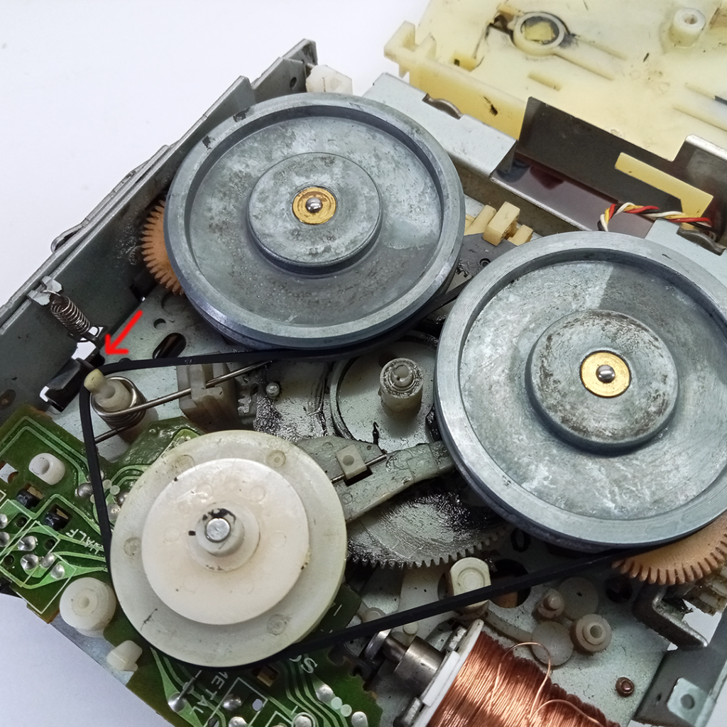
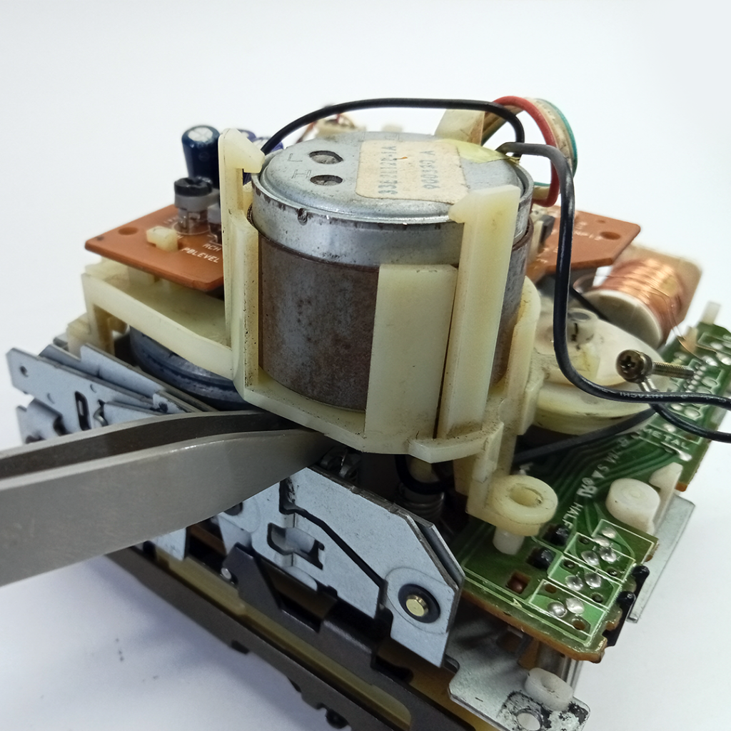
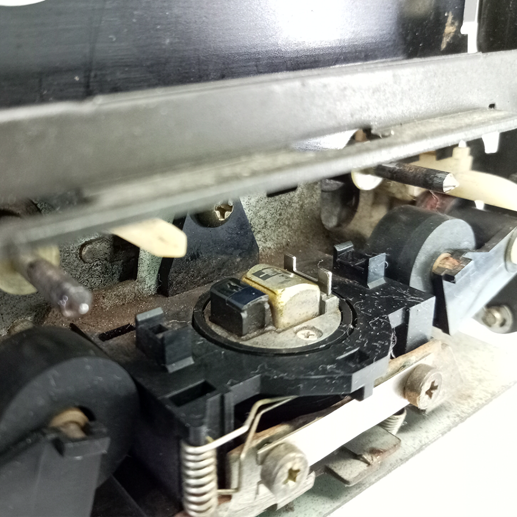
Deck A was not functioning due to a broken drive belt. I ordered a new 100mm belt and replaced it, which restored its functionality. However, the replacement process was a bit challenging. First, loop the belt around the spring stay as illustrated, then reposition the drive motor assembly. Using a pair of pinchers or tweezers, carefully hold the belt and loop it over the motor drive pulley.
Guide to replacing the drive belt l Guide to measure the belt
Mounting Cassette Decks
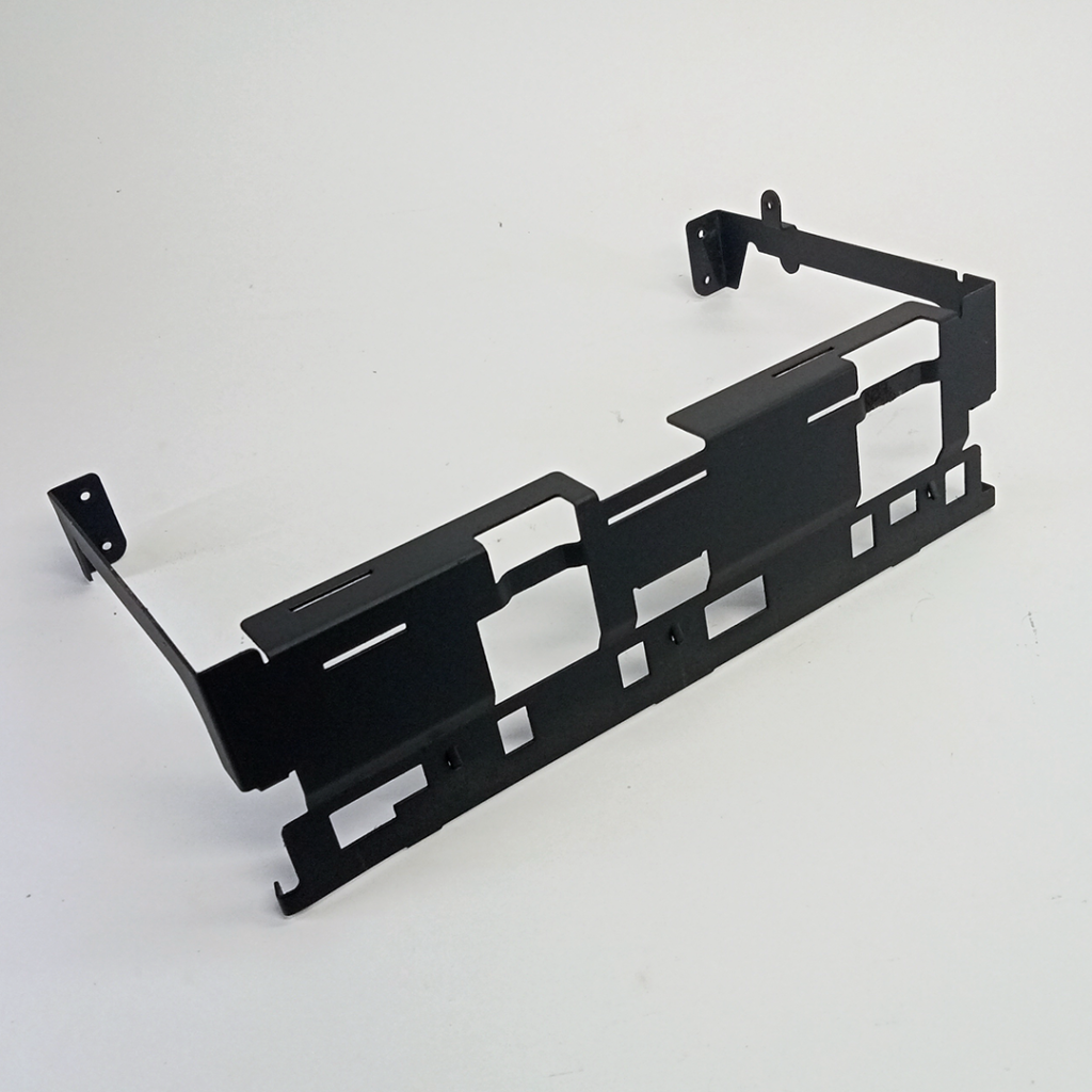
The cassette deck holder frame is used to mount Decks A and B, and this frame, along with the decks, is secured onto the chassis.
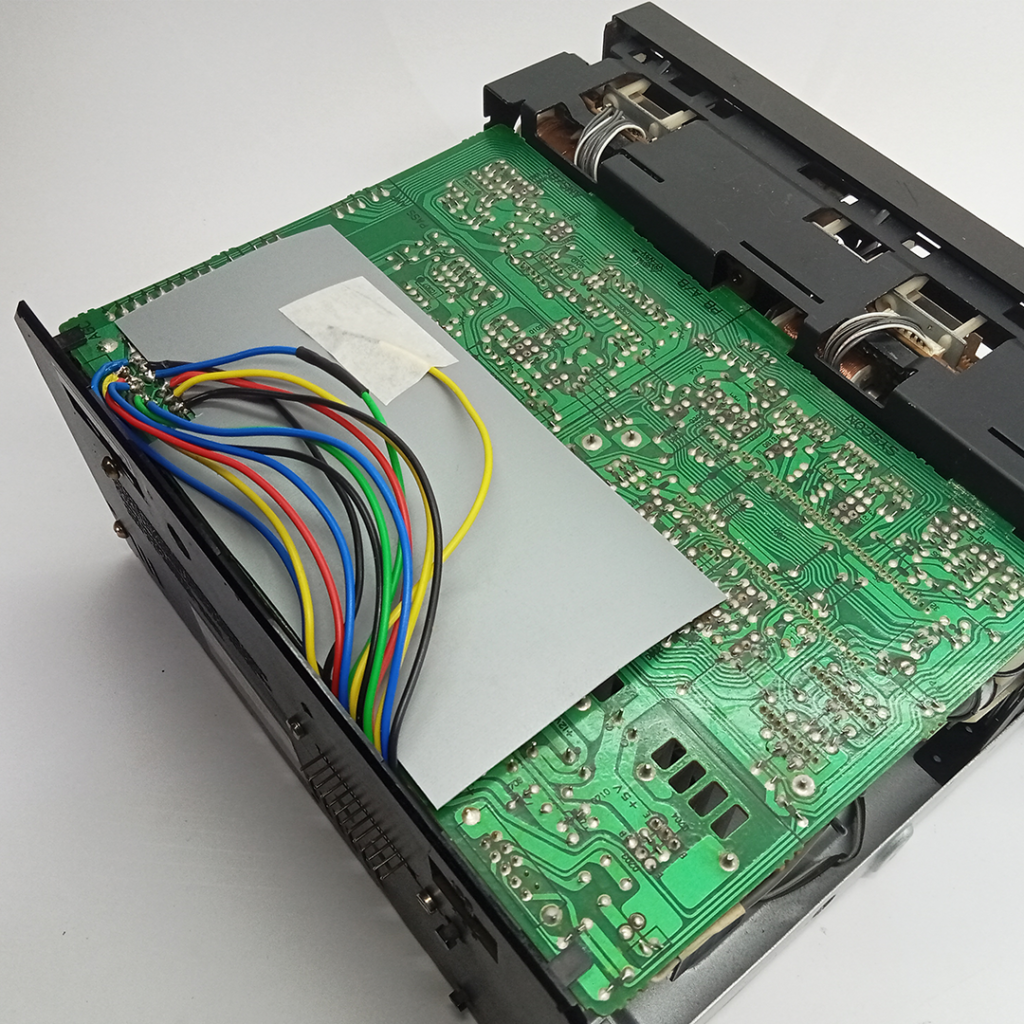
Cassette Deck Audio Boards
Audio Board A (Larger Board) is equipped with the MC14053BCP, a quad analog multiplexer/demultiplexer IC used for audio switching and signal routing. This IC functions as the AMS (Automatic Music Sensor) for Decks A and B. Additionally, the RC4458P, a dual low-noise operational amplifier, serves as the AMS amplifier. The board also features the M50964-223SP, a system control EPROM microcomputer built with CMOS technology, and power supply section.
Audio Board B features the CX20187, which provides complete stereo Dolby B and C noise reduction processing. This board also includes the MC14051BCP, which consists of analog multiplexers and digitally controlled analog switches. And the IC CXA1198AP integrates various audio processing functions, handling the encoding and decoding of audio signals according to Dolby standards, contributing to clearer, higher-quality audio reproduction. This IC also serves as the record equalizer select, allowing users to choose the appropriate equalization settings for the type of tape being used during recording.
Cassette Deck Key Board
This control panel manages the primary functions such as play, reverse, fast forward, rewind, Dolby switch, recording settings, and the cassette holder release switch, among others.
Customized Female Socket and Male Pin
I customized a 17-pin female socket and male pin for the ribbon strip wire of the main system control connection because the original components were broken and exact replacements were unavailable. To achieve this, I used a Berg strip pin and socket. The socket features 17 pins for multiple signal connections, facilitating control signals for playback, recording, and other operations.
3. CD Player, Model: CDP-S39
In my Sony MHC-2500 Mini Hi-Fi System the power board for the CD player was completely burnt, though the CD load unit and main board remains intact. Since replacing or rebuilding the power board is challenging, I decided to repurpose the system as an AUX/Line-in with an added audio filter for clearer output. The CD unit has a transformer that provides 30V, 10V, and 3V AC outputs. I built a circuit to convert the 30V into +12V and -12V and designed an audio filter circuit powered by this supply. The filtered audio output is then fed into the receiver unit.

Customized system control connector, using male and female berg strip.
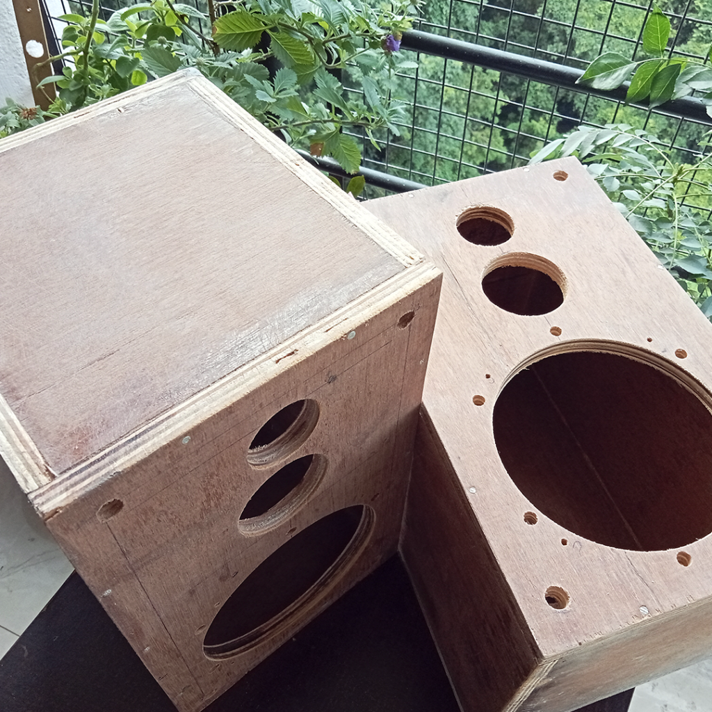
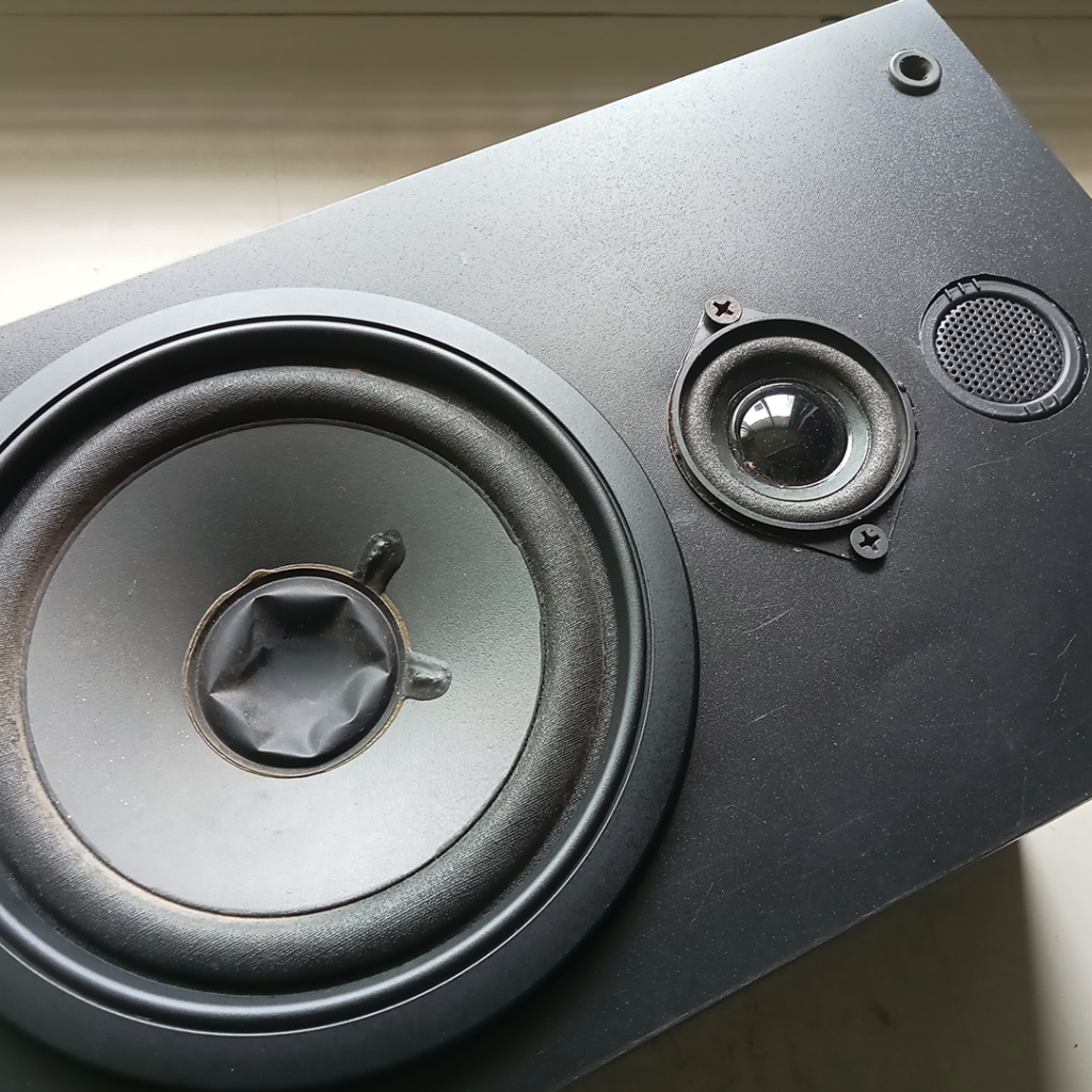
4. Speaker System Model: SS-H2500
The enclosures of the R&L channel speaker were partially damaged at the rear due to water absorption, as they were made of MDF board. To replace them, I built two new enclosures using plywood. Additionally, since a 2-inch paper cone mid-range speaker was unavailable, I opted for a normal 2-inch, 10W speaker. I also upgraded the piezo tweeter to a dome tweeter.
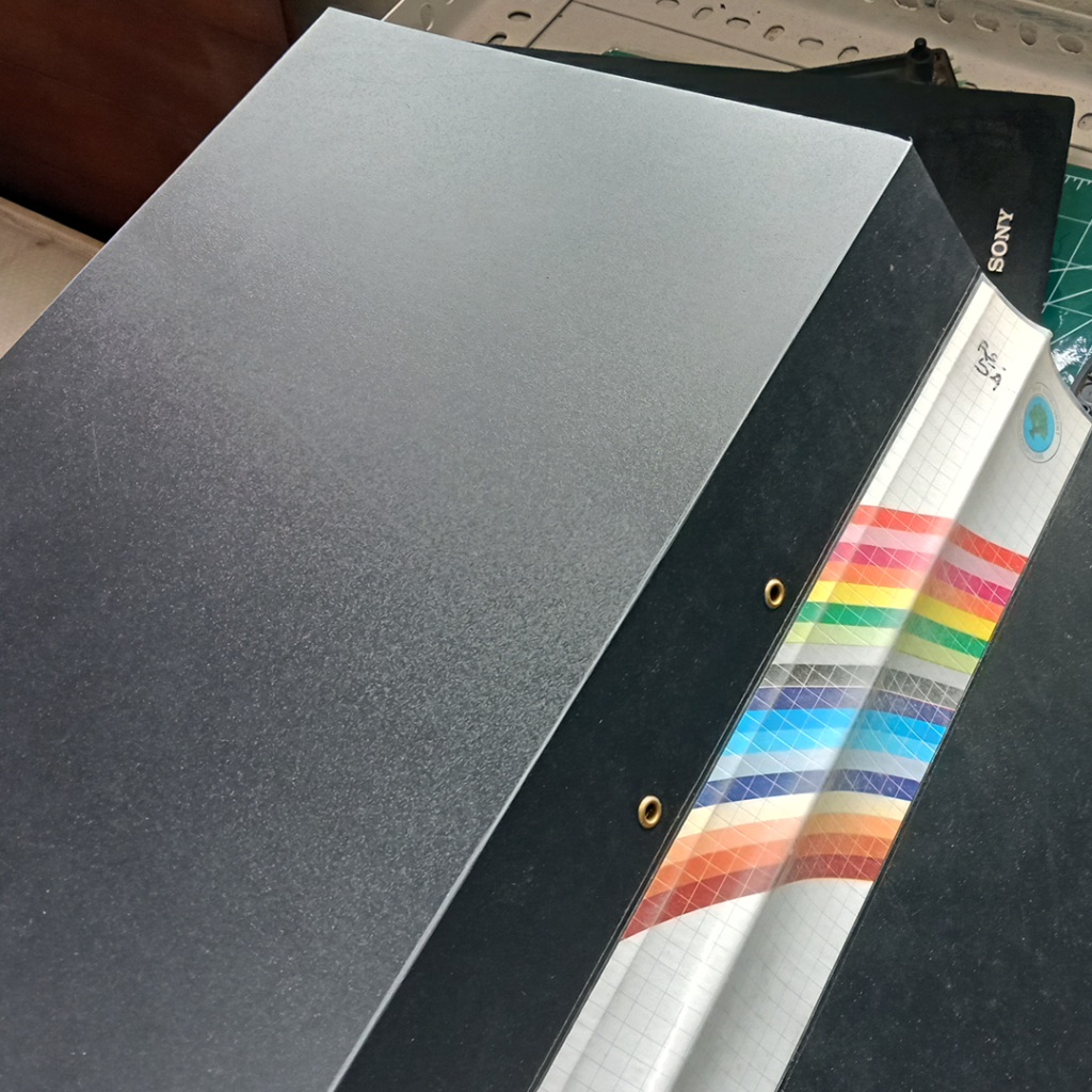
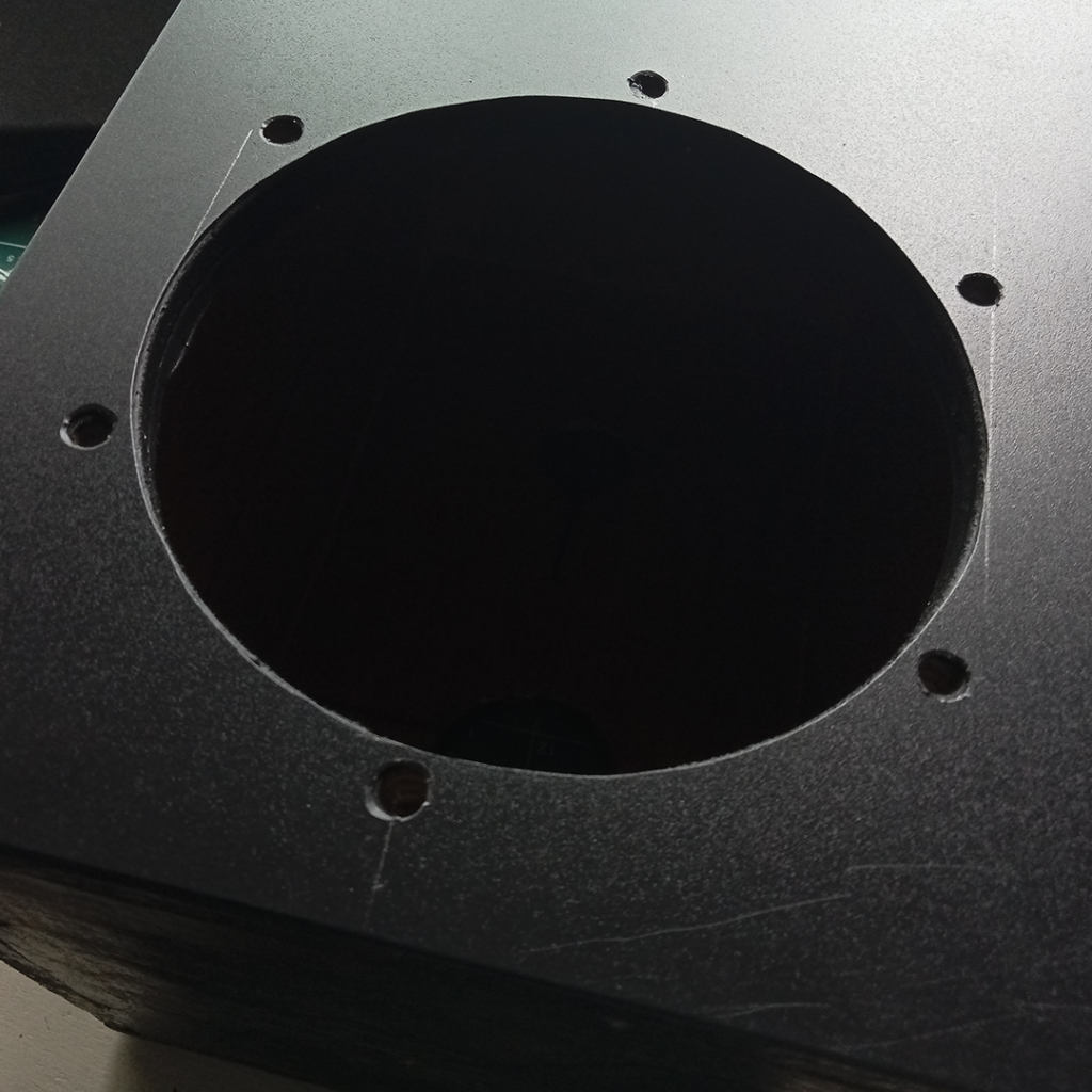
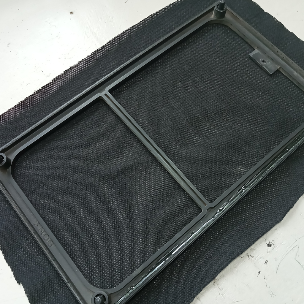
Fabrication
To achieve an original look, I fabricated the front side of the enclosure by using material from a plastic office file/folder after applying two coats of black matte spray paint.
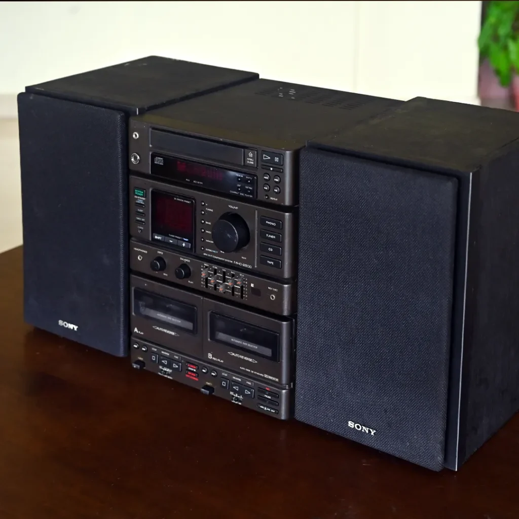
My Sony MHC-2500 Hi-Fi system—final look.
Find Sony MHC-2500 Service Manual here